XRGI
®
- INSTALLATION GUIDE
VERSION 1.0 2018
14
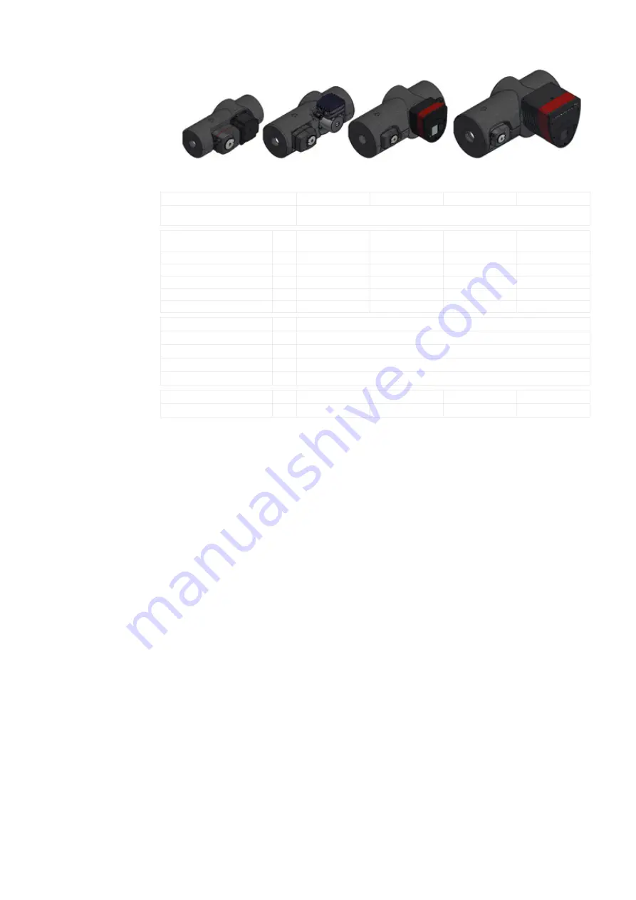
The Flow Master feeds the heat from the XRGI® system and from the storage tank into the consumer circuit. In the short term, this
allows significantly higher heating capacity on the consumer side than with the installed XRGI® heating line. With this, heat demand
peaks can be handled by the XRGI® system, thus extending its production time and increasing heating capacity.
Four models are currently available that can operate at a ΔT of 20 K with a heat output of 50, 150, 250 or 350 kW. The desired flow
temperatures (up to a maximum of 79.9 °C) are constantly available. The injectable heat output is adjusted automatically depending
on the return temperature from the property‘s network. The decision about which Flow Master to be used with Flow Master Control
is determined according to the building conditions and the consumption habits.
When using a Flow Master with a Flow Master Control, the instructions on the temperature sensors, the injection line and the sizing
of the heating pipes are to be complied with to ensure correct operation.
SCOPE OF DELIVERY
FM type (temperature controller, class II = 2 %)
FM 50
FM 150
FM 250
FM 350
Modules
Flow Master, Flow Master Control Unit, four PT100 sensors, one Q-Network cable,
one valve control cable, one pump control cable and one power cable
DATA
Pump
UPM3
15-75 130
UPMXL GEO
25-125 180
Magna3
50-60 F 220
Magna3
50-60 F 240
Flow connection
G
¾"
1 ¼"
1 ½"
2"
Temperature sensor
PT100 (5 x 40 mm)
PT100 (5 x 40 mm)
PT100 (5 x 40 mm)
PT100 (5 x 40 mm)
Maximum flow volume
m
3
/h
2.2
6.5
10.8
15.1
Thermal capacity
kW
50
150
250
350
ΔT (with a return of 60–65 °C)
°C
20
20
20
20
CABLE DIMENSIONS
PT100 sensor cable
m
3
Valve control cable
m
1.8
Pump control cable
m
1.8
Power cable
m
1.8
Q-Network cable
m
5
DIMENSIONS
AND WEIGHT
Dimensions, W x H x D
mm
157 x 120 x 323
181 x 196 x 411
297 x 221 x 483
407 x 273 x 512
Weight
kg
2.9
5.4
17.2
27.1
2.2.1.3 F L O W M A S T E R
Fig. 2.22 - Flow Master


