


Publication No.: 2753-20
4
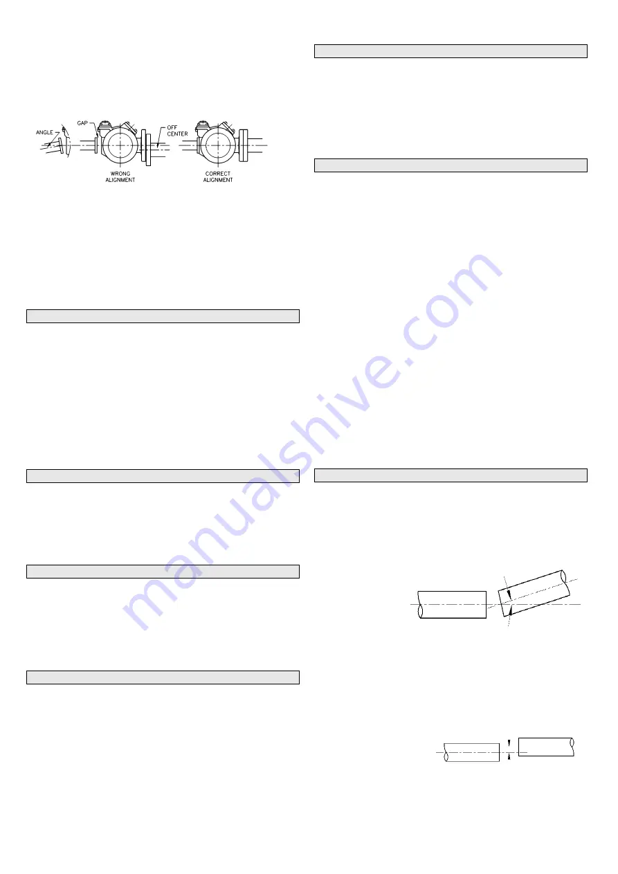
4. Check alignment of pipes to pump to avoid strains which
might later cause misalignment. See Figure 1. Unbolt
flanges or break union joints. Pipes should not spring away
or drop down. After pump has been in operation for one to
two weeks, completely recheck alignment.
NOTE:
Pumps with welded connections contain non-metallic O-
ring seals that will be damaged if welding is done with
these O-rings installed.
Prior to welding the piping, remove the O-rings from under the
alternate inlet flange and discharge flange. After the welding is
complete, reinstall the lubricated O-rings into the cleaned O-
ring grooves.
3.5
R75/R77 - ALTERNATE INLET
The R75 and R77 have an alternate inlet port can be used as a
fill connection for bottom loading of the tank by stationary
pumps at the terminal or bulk plant. It can also be used as an
alternate pump inlet, allowing the pump to unload another tank.
The Alternate Inlet can be used to remove liquid from end user
tanks prior to removal/inspection. As such, it is recommended
that Alternate Inlet must be connected through a suitable
strainer using a minimum 40 mesh strainer screen.
To minimize vapor formation, the alternate inlet line must
minimum DN50 and as short as possible.
3.6
PRE-INSTALLATION CLEANING
NOTE:
New pumps contain residual test fluid and rust inhibitor. If
necessary, flush pump prior to use.
The supply tank and intake piping MUST be cleaned and
flushed prior to pump installation and operation.
3.7
PUMP ROTATION
NOTE:
Confirm pump rotation by checking the pump rotation
arrows respective to pump driver rotation.
The pump rotation is always clockwise looking from the shaft
end. See SECTION 6.1 for instructions for re-handing the
pump.
3.8
CLOSE-COUPLED DRIVES
R75, R77, R80 and R82 pumps are designed to be close
coupled to hydraulic motors and electric motors. The motors
should be well supported with their shafts parallel to the pump
shaft in all respects.
Ebsray can provide optional close-coupled hydraulic motor and
electric motor adapters. These adapters provide straight
alignment of the motor drive through a coupling connected to a
straight key pump shaft.
3.9
LONG COUPLED AND BELT DRIVES
The R80 and R82 pumps are also designed to be long coupled
driven and belt driven.
Long coupled drives should be well supported with their shafts
parallel to the pump shaft in all respects.
Belt drives should be well supported with their shafts parallel to
the pump shaft and should minimise radial load on the pump
shaft.
3.10
PUMP INTERNAL RELIEF VALVE
NOTE:
When fitted, the pump internal relief valve is designed to
protect equipment from excessive pressure and must not
be used as a system pressure control valve or operational
bypass valve.
NOTE:
Non-UL Listed Pumps (e.g. ATEX Marked Pumps) are
normally supplied without the internal relief valve (Blank-
No Valve is marked on the pump). An external pressure
limiting system valve is required for these variants.
For ALL liquefied gas applications, install an external bypass
valve which must have a free and clear passage back to the
tank.
DO NOT pipe the External Bypass Valve back into the
pumps’
inlet line.
External Bypass Valves are vital to the performance and
operation of liquefied gas pumps and control the maximum
operating differential pressure of the system.
If the pump is fitted with an Internal Relief Valve, the
differential pressure setting on the external bypass valve must
not exceed 1400 kPa (14 Bar).
3.11
COUPLING ALIGNMENT
To maximise the life of the pump appropriate alignment of the
coupled shafts is a fundamental requirement of any coupling
installation. If pump was supplied by Ebsray as part of a pumpset
unit, pump and driver have been accurately aligned at factory.
To ensure that alignment has been maintained during transit and
installation,
alignment
MUST
BE
CHECKED
upon
final
installation and prior
to startup.
Ensure
‘distance
between shaft ends’
(DBSE) is correct for the type of coupling utilised.
Angular misalignment
As shown in Figure 2 where shafts are at an angle to one
another should be corrected before parallel misalignment.
Parallel misalignment
As shown in Figure 3
where shafts are in line
angularly and parallel to
each other but are offset
must be corrected.
Figure 1:
Pipe alignment
Figure 2
Figure 3
Summary of Contents for R75
Page 11: ...Publication No 2753 20 11...
Page 13: ...Publication No 2753 20 13...