


Operating and Maintenance Instructions
210-OMI14229-Iss8.1
CN1116 Full OMI
Page 9 of 47
© ebm-papst UK Ltd 2021
Chelmsford Business Park Chelmsford Essex CM2 5EZ
Telephone: +44(0)1245468555 Fax: +44(0)1245466336
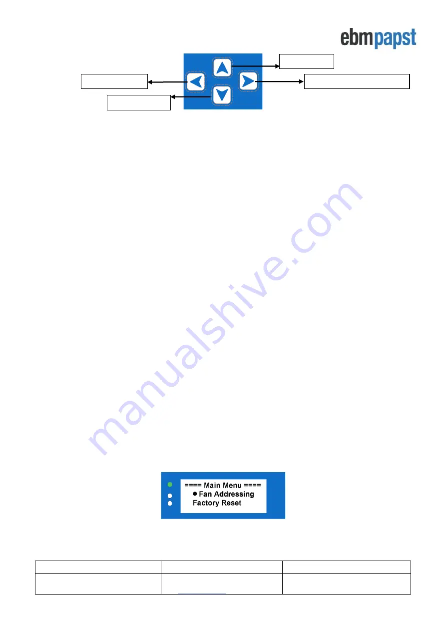
Figure 4 - Keypad buttons
•
The FORWARD / ENTER button
moves forward to the next fan if monitoring a fan’s status screen or
confirms the request / change of a set value when configuring parameters inside the menus.
•
The UP and DOWN buttons navigate through
fan parameters when monitoring a fan’s status screen or
changes the setpoints inside the menus.
•
The BACK button moves back one step in the software structure without saving any changes made.
The menu structure flow chart is shown in
Once the controller is configured and about to start normal operation, the green LED status indicator will be switched
on and the controller will display the real time operating condition of the fans. It is possible to scroll through the
network of connected fans to check set points, power consumption, alarm conditions and fan warnings from each
fan by using the keypad interface.
When a fan enters an alarm state or has lost communication with the controller, the red LED status indicator will
switch on and the display will show the fan that is experiencing the alarm as well as the details about that alarm.
If another fan in the array enters an alarm state, the controller will automa
tically display that fan’s alarm screen in
order to always display the most recent fan experiencing a fault.
If a warning condition has been detected in any fan, the controller will illuminate the yellow fan status indicator LED
but the display will not automatically show which fan has raised the warning. Fans that have entered a warning
condition status can be found by navigating through the network of connected fans using the keypad buttons or by
processing the
controller’s
Modbus registers using an external Modbus Master device connected to the
controller’s
RS485 Slave port.
4.3 First time controller configuration
The controller can be used on a new installation with fans delivered in their factory default condition or be used on
an existing array of fans which have been networked and pre-addressed by another MDC. If the controller is used
in a fan array previously configured by another device, in most cases it is only
required to use the controller’s
“Factory Reset”
option before configuring the controller and fans.
4.3.1 Configuring the controller with fans that are in their factory default settings
New fans are typically supplied with factory default Modbus address 1 and factory default Modbus Port
Configuration of 19200 baud rate, even parity and 1 stop bit. New controllers are supplied without any stored fan
array configurations and on first application of power to the controller, the Main Menu will be displayed as shown in
Figure 5 below:
Figure 5 - Main menu display screen on first application of power
For the controller to locate and address the fans in the network, all fans must be factory default Modbus Address 1
and with one of the supported Modbus Port Configuration shown in Table 3 below:
FORWARD / ENTER button
UP button
BACK button
DOWN button


