background image

10

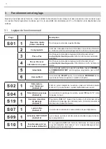
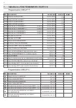
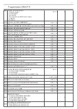
S 02 1

Refermeture 

pour l’allumage

(Default 0)

il fait un cycle complet de ouverture, pause et fermeture seule

-

ment si il n’y a pas tension, quand l’automation es ouvert. 

S 04 1

Relevation du passage

(Default 0)

Au relevation du passage de cellule, quand 

S19

 est à “

0

”, temp 

de pause à 2 sec.

S 19 1

Inversion relevation 

du passage

(Default 1)

Programmer 

S04 à 1

. Quand il est activée le fonctionnement au 

relevation du passage des cellules ouvre, l’armoire renverse la 

direction des moteurs et ferme.

S 07 1

lumière fixe

(Default 0)

La sortie de la lumière fixe reste allumée et pas clignotante.

S 09 1

 Activation SoFT START 

(Default 0)

Les moteurs au debut ont des valeurs standard jusqu’à les va

-

leurs programmés.

S 10 1

Fonctionnement d’un 

seul moteur 

(Default 0)

Si on programme 

S10 à 0

, l’armoire fait toutes les manoeuvres 

en synchronisation du moeteur 1 et 2. L’apprentissage est pro

-

grammé pour le seul moteur 1.

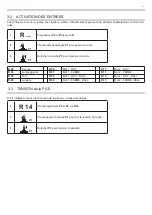
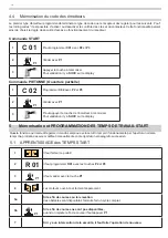
Fonctionnement et reglage

Progr.

description

S 01 1

 Reversion rapide

(Valeur standard)

Par chaque commande: 

ouvre - ferme.

2

Comproprieté

L’armoire n’accepte aucune commande en ouverture et fermetu

-

re, l’armoire referme automatiquement à la fin du temp de pause.

3

Pas au Pas

Par chaque commande la logique de fonctionnement est  

ouvre-stop-ferme-stop-ouvre.

 Elle ne referme pas automati

-

quement.

4

Pas au Pas avec 

refermeture à la pause

Par chaque commande la logique de fonctionnement est: 

ouvre-stop-ferme-stop-ouvre

. Elle referme à la fin du temp de 

pause.

5

Industrielle

La commande pietonne (ouverture partielle) devient 

fERME

 et 

la 

COMMANDE START

 suit la logique programmé par le DiP1 

et DiP2

6

Homme mort

La commande 

START

 ouvre, la commande 

PiETONNE

 ferme. 

Les moteurs ferment quand on relâche le touche.

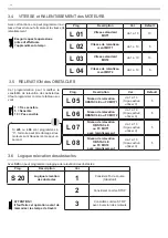
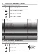
3.1  Logique de fonctionnement

Quand le branchement est terminé, il faut contrôller le branchement des moteurs et des accessoires comme dans le par. 

4.2, après il faut programmer la vitesse par. 4.4, la sensibilité des obstacles par 4.5  et l’activation et la déactivation des 

entrées.

Summary of Contents for START S10

Page 1: ...5 14 13 Ingresso 230 Vac da rete Ingresso 230 Vac da rete 28 27 Uscita ALIMENTAZIONE 29 Uscita ALIMENTAZIONE 30 Comune Servizi e Sicurezze 11 22 23 24 25 MOT 1 BATTERIA BATTERIA Ingresso BASSA TENSIONE 1 12 Fine corsa CHIUDE 2 Ingresso BASSA TENSIONE 26 M M MOT 2 MOT 1 2002 95 EC RoHS C O M P L I A N T 230 Vac TX RX TX RX Fotocellule attive sulla chiusura Fotocellule attive sia in chiusura che in ...

Page 2: ...apparecchiature in Vostro possesso Vi invitiamo a contattare gli enti pubblici di competenza il servizio di smaltimento rifiuti o il negozio nel quale avete acquistato il prodotto 1 Introduzione 3 1 1 Descrizione prodotto 1 2 Caratteristiche tecniche 2 Premesse 2 1 Verifiche preliminari 2 2 Tipologia cavi elettrici 4 2 3 Impianto tipo 2 4 Note sui collegamenti 2 5 Schema della centrale e dei colle...

Page 3: ...e nella centrale solo dal lato inferiore si raccomandano pressacavi e raccordi stagni Nel caso si usino tubazioni soggette a riempirsi d acqua o se queste tubazioni provengono da un pozzetto interrato è necessario far entrare i cavi in una prima scatola di derivazione posta alla stessa altezza della centrale e poi da questa sempre dal lato inferiore passare i cavi dentro il contenitore della centr...

Page 4: ... per prevenire danni ai componenti mentre si effettuano i collegamenti o si innesta la scheda radio ricevente la centrale deve essere assolutamente non alimentata Alimentare la centrale attraverso un cavo da 3 x 1 5mm2 Se la distanza fra la centrale e la connessione all impianto di terra supera i 30m è necessario prevedere un dispersore di terra in prossimità della centrale Se i motori sono sprovv...

Page 5: ... R oppure selezionare E per ritornare al funzionamento normale Dopo circa 60 secondi di inutilizzo delle impostazioni la centrale esegue un AUTORESET e ritorna al funzionamento normale Utilizzare sempre P1 per confermare P2 e P3 per scegliere il nu mero di impostazione per ritornare indietro alla scelta del gruppo di impostazione premere P2 P3 A COLLEGAMENTO ULTIMATO Controllare il corretto verso ...

Page 6: ...itivi di arresto STOP Collegamento del comando STOP Pulsante arresta ed inibisce momentaneamente fino a nuovo comando Interruttore mantiene l automazione bloccata fino a nuovo ripristino dello stesso Se l ingresso STOP non viene utilizzato settare a 0 l impostazione S 15 29 27 30 28 Primario TRASFORMATORE 230V Ingresso BASSA TENSIONE da trasformatore BATTERIA Il collegamento dei dispositivi di sic...

Page 7: ...nche nel tem po di pausa Val Default 0 Per attivare la funzione lampeggiante in pausa settare a 1 come da tabella l impostazione S05 per disattivare setta re l impostazione a 0 Settare l impostazione S25 a 1 se si usa un lampeggiante senza scheda di intermittenza altrimenti settare S25 a 0 3 8 PRELAMPEGGIO Per aumentare o diminuire il tempo di prelampeggio in condizione di aperto o chiuso settare ...

Page 8: ...ivazione Ingresso FC2 Val di Default 1 S 14 0 Disattivazione Ingresso FCC2 Val di Default 1 3 11 Collegamento di un comando di APERTURA START PEDONALE 3 4 5 6 7 8 9 10 11 12 Il collegamento del comando di apertura START può essere effettuato a qualsiasi pulsante o contatto di tipo N A normalmente aperto Se vi sono più dispositivi vanno collegati in parallelo Utilizzando i morsetti 3 e 11 è possibi...

Page 9: ... tensioni di alimentazione tipo N C normalmente chiuso Se si utilizzano più coppie di foto cellule il collegamento deve essere in serie Il TEST sulle fotocellule assicura il funzionamento dell automazione solo se le fotocellule funzionano regolarmente La centrale infatti eseguirà il test prima di ogni apertura In caso di malfunzionamento delle fotocellule la centrale accenderà per 5 secondi il lam...

Page 10: ...solato dalle tensioni di alimentazione tipo N C normalmente chiuso Se si utilizzano più coppie di foto cellule il collegamento deve essere in serie Se l ingresso FOTO non viene utilizzato deve essere settata a 0 l impostazione S16 Il TEST sulle fotocellule assicura il funzionamento dell automazione solo se le fotocellule funzionano regolarmente La centrale infatti eseguirà il test prima di ogni ap...

Page 11: ...tare la funzione S26 e S28 a seconda dell installazione 3 18 Collegamento MOTORE con BLOCCO ELETTROMAGNETICO Se il motore dispone del blocco elettromagnetico settare a 1 la funzione S26 e seguire quanto riportato Impostazione Val Descrizione S 26 1 Abilita funzione SBLOCCO FRENO Impostazione Descrizione S 26 0 Abilita SERRATURA 1 Disabilita SERRATURA Default S 28 Potenza SERRATURA 0 Con serratura ...

Page 12: ... 1 L apprendimento tempi viene effettuato per il solo motore 1 4 Modi di funzionamento e regolazioni Impostazione Funzione Descrizione S 01 1 Inversione rapida Valore di default Ad ogni comando inverte apre chiude 2 Condominiale In apertura ed in pausa non accetta comandi richiude automati camente al termine del tempo di pausa 3 Passo Passo Ad ogni comando segue la logica apre stop chiude stop apr...

Page 13: ...disattivare l uscita P1 P1 R 02 Serratura R 06 Mot 1 AP R 10 Mot 2 AP R 03 Lampeggiante R 07 Mot 1 CH R 11 Mot 2 CH R 04 Test R 08 Mot 1 AP RALL R 12 Mot 2 AP RALL R 05 Spia R 09 Mot 1 CH RALL R 13 Mot 2 CH RALL 4 3 Visualizzazione TENSIONE BATTERIA La centrale consente di visualizzare tramite Display la tensione della batteria oppure se la batteria è in carica 1 R 14 Posizionarsi tramite i pulsan...

Page 14: ...lo Rilevamento Ostacoli o FC MOT2 da 1 a 10 se 0 Disattivato 5 L 07 Livello Rilevamento Ostacoli o FC MOT1 in Rallentamento da 1 a 10 se 0 Disattivato 5 L 08 Livello Rilevamento Ostacoli o FC MOT2 in Rallentamento da 1 a 10 se 0 Disattivato 5 4 6 Logica RILEVAZIONE OSTACOLI Settando l impostazione S20 si può impostare la logica di rilevazione degli ostacoli Impostazione Descrizione Valori S 20 Log...

Page 15: ...o ad automazione in posizione di CHIUSO Impostazione Descrizione C 03 Reset memoria codici Per effettuare la cancellazione dei codici segliere l impostazione C03 utilizzando i pulsanti P2 e P3 Poi confermare con il tasto P1 Atten dere 10 secondi come indicato dal DISPLAY se viene premuto il tasto P1 durante questi 10 secondi l operazione viene annullata 5 2 CANCELLAZIONE di un singolo codice radio...

Page 16: ...i pulsanti P2 e P3 sull impostazione C02 2 Confermare premendo il tasto P1 3 Premere il pulsante del radicomando da apprendere Ad apprendimento avvenuto visualizzare SUCC sul DISPLAY P1 1 Posizionare l automazione in condizione di chiuso 2 R 01 Posizionarsi tramite i pulsanti P2 e P3 sull impostazione R01 3 Confermare premendo il tasto P1 4 La centrale esegue l apertura e la chiusura separata dei ...

Page 17: ...nto in APRE da 2 a 127 5 s 2 s T 10 Tempo sfasamento in CHIUDE da 2 a 127 5 s 2 s T 11 Tempo pausa per comando START da 2 a 127 5 s 10 s T 12 Tempo apertura MOT1 comando PEDONALE da 2 a 127 5 s 8 s T 13 Tempo chiusura MOT1 comando PEDONALE da 2 a 127 5 s 8 s T 14 Tempo pausa per comando PEDONALE da 2 a 127 5 s 10 s T 17 Tempo funzionamento SERRATURA da 0 a 10 s 2 s T 19 Tempo COLPO D ARIETE inizia...

Page 18: ... da 2 a 127 5 s 8 s T 14 Tempo di PAUSA per comando PEDONALE da 2 a 127 5 s 10 s T 15 Tempo di PRELAMPEGGIO alla partenza da chiuso da 0 a 10 s 2 s T 16 Tempo di PRELAMPEGGIO in condizione di aperto da 0 a 10 s 2 s T 17 Tempo di funzionamento SERRATURA da 0 a 10 s 2 s T 18 Tempo di funzionemnto LUCE di CORTESIA da 2 a 127 5 s 120 s T 19 Tempo COLPO D ARIETE 0 per disattivare da 0 a 10 s 0 s T 20 T...

Page 19: ...e Ingresso FCC2 0 Off 1 On 1 S 15 Attivazione Ingresso STOP 0 Off 1 On 1 S 16 Attivazione Ingresso FOTO 0 Off 1 On 1 S 17 Attivazione Ingresso FOTOSTOP 0 Off 1 On 1 S 18 RESET Impostazioni centrale a volari DEFAULT S 19 Attivazione INVERSIONE su rileca passaggio S 04 1 0 Off 1 On 1 S 20 Logica RILEVAZIONE OSTACOLI 1 Considera come FINECORSA 2 Considera STOP 3 Considera STOP preceduto da inversione...

Page 20: ... 04 Attiva TEST fino al rilascio di P1 R 05 Attiva SPIA fino al rilascio di P1 R 06 Attiva APRE MOT1 fino al rilascio di P1 R 07 Attiva CHIUDE MOT1 fino al rilascio di P1 R 08 Attiva APRE MOT1 in rallentamento fino al rilascio di P1 R 09 Attiva CHIUDE MOT1 in rallentamento fino al rilascio di P1 R 10 Attiva APRE MOT2 fino al rilascio di P1 R 11 Attiva CHIUDE MOT2 fino al rilascio di P1 R 12 Attiva...

Page 21: ...NOTE 21 ...

Page 22: ...NOTE 22 ...

Page 23: ...egislazioni degli Stati membri relative alla compatibilità elettromagnetica Riferimento alle norme armonizzate EN 61000 6 2 EN 61000 6 3 IL PRODOTTO E CONFORME ai requisiti essenziali richiesti dall articolo 3 dalla seguente direttiva comunitaria per l uso al quale i prodotti sono destinati 1999 5 CE DIRETTIVA 1999 5 CE DEL PARLAMENTO EUROPEO E DEL CONSIGLIO del 9 marzo 1999 riguardante le apparec...

Page 24: ...ilié du constructeur et si applica ble de son représentant autorisé Busto Arsizio Va Italia 01 10 2010 ERNESTINO BANDERA Administrateur KONFORMITÄTSZERTIFIKAT Der Unterzeichner bescheinigt dass das Produkt allen technischen Produktegesetzen laut den Europäische Gesetzen 2006 95 CE 99 5 CE e 2004 108 CE entspricht Alle Radiofrequenzprüfungen haben bei der nachstehenden Firma stattgefunden EB TECHNO...

Page 25: ...c input 28 27 Output for power supply 29 Output for power supply 30 Common Services and Safeties 11 22 23 24 25 MOT 1 BATTERY BATTERY Input for low tension 1 12 CLOSING limit switch 2 Input for low tension 26 M M MOT 2 MOT 1 2002 95 EC RoHS C O M P L I A N T 230 Vac TX RX TX RX Photo beam activated when closing Photo beam activated when opening and closing Connect this point to the terminal board ...

Page 26: ... purchased the product 1 Introduction 3 1 1 Description of the produc 1 2 Technical caracteristics 2 Premises 2 1 Preliminary checks 2 2 Type of cable 4 2 3 Installation 2 4 Notes of connections 2 5 Scheme of the control unit and electrical connections 5 3 Installation of the control unit 6 3 1 Connection of the POWER SUPPLY 3 2 Connections of the MOTORS 3 3 Connection of the ANTENNA 3 4 Power sup...

Page 27: ...f the ground The cables must enter the control unit from the bottom only we recommend using wire leads and water tight connections When using tubing that could fi ll up with water or if the tubing comes from an underground well the wires must enter a fi rst shunting box placed at the same height as the control unit and then from there the wires must be passed into the container holding the control...

Page 28: ...g 2 4 Notes on connections To guarantee operator safety and to prevent damaging the components never make connections or insert wireless receiver boards while the control unit is powered Power the control unit through a 3 x 1 5 mm cable If the distance between the control unit and the ground system connection is more than 30 m a ground plate must be installed in proximity to the control unit If th...

Page 29: ...elect different groups T L S C R or select E to go back to the standard function The control unit will reset all functions and go back to the normal status after 60 seconds which is unsed Press P1 to confirm the operation P2 and P3 to choose the set up if you need to go back to the group of set up press P2 P3 WHEN THE CONNECTION IS FINISHED When the connection is finished check the motors as shown...

Page 30: ...a new control If the input STOP is not used put 0 in the set up S15 29 27 30 28 230V input Primary Transformer Low Tension input for transformer BATTERY Connection of the safety devices requires the use of any push button or N C normally closed contact When there are several safety devices they are connected in series 3 4 5 6 7 8 9 10 The power supply line has to be protected from a magneto termic...

Page 31: ...light is working in the pause time too Standard value 0 To activate the function lamp during pause time put S 05 at 1 to deactivate the function put S05 at 0 Put the set up S25 at 1 if you use a lamp without flashing light otherwi se put the S25 at 0 3 8 PRE LIGHTING To increase or reduce pre lighting time put T 15 and T 16 as follow Set up Description T 15 Pre lighting time when CLOSED Set up fro...

Page 32: ...ription S 13 0 Deactivation of the input opening limit switch 2 Standard value 1 S 14 0 Deactivation of the input closing limit switch 2 Standard value 1 3 11 Connection of an OPENING CONTROL START PARTIAL OPENING 3 4 5 6 7 8 9 10 11 12 The connection of a START can be done with every button or a normally open contact If more devices are available they should be serial connected If you use the ter...

Page 33: ...oset contact of the receiver should be isolated from tensions If you you more couples of photo beams the connection should be serial The PHOTO TEST check the right working of the gate if the photo beams are working properly The control unit will do a test before the gate opening In case the photo beams are not working properly the lamp will be turned on and the gate is not working If the input FOT...

Page 34: ...ons If you you more couples of photo beams the connection should be serial If the input PHOTO STOP is not used put the S16 at 0 The PHOTO TEST check that the gate is working only if the photo beams are working properly The control unit will do a general test before opening In case the photo beams are not working properly the signal light will turn on for 5 seconds and the gate is not working Set u...

Page 35: ...ro magnetic bloc MOT MOTOR BRAKE 17 18 19 13 14 15 16 When this function will be activated and the motor is working the output of the KEY LOCK will be powered this permet the brake and the correct working of the gate 3 16 Connection of the KEY LOCK NEW LOCK SYSTEM 17 18 19 13 14 15 16 Here you can see the connections of the key lock The function S 26 should be programmed to 0 Set up Description S ...

Page 36: ...o 1 4 Function and adjustment Set up Function Description S 01 1 Fast reverse Standard value By each control it riverse open close 2 Collective use When opening and pause time it doesn t accept any control it re close automatically 3 Step by step function Each control it follows each open stop close stop open No automatic reclosing 4 Step by step with automatic re closing after pause time By each ...

Page 37: ... P1 R 02 Key lock R 06 Mot 1 OP R 10 Mot 2 OP R 03 Lamp R 07 Mot 1 CL R 11 Mot 2 CL R 04 Test R 08 Mot 1 OP SLOW DOWN R 12 Mot 2 OP SLOW DOWN R 05 Light R 09 Mot 1 CL SLOW DOWN R 13 Mot 2 CL SLOW DOWN 4 3 Check the battery tension The control unit can check with the display the tension of the battery or if the battery is charged 1 R 14 Press the P2 and P3 in the function R14 2 Keep pressed the but...

Page 38: ...o 10 0 deactivation 5 L 07 Level of obstacle detection o LS MOT1 in case of slow downfrom from 1 to 10 0 deactivation 5 L 08 Level of obstacle detection o LS MOT2 in case of slow downfrom from 1 to 10 0 deactivation 5 14 4 6 Logic of OBSTACLE DETECTION If you use S20 you can set up the obstacle detection Set up Description Values S 20 Logic of obstacle detection 1 LIMIT SWITCH FUNCTION standard fu...

Page 39: ...nofonesinglecodeispossiblewhenthe gate is CLOSED Set up Description C 03 Reset of the memory code To cancel the memory code choose C03 with button P2 and P3 Then confirm the operation with P1 Wait 10 seconds as indicated in the DISPLAY if the button P1 will be pressed in these 10 seconds the operation will be cancelled 5 2 CANCELLATION of a SINGLE CODE This operation cancell one single code in the...

Page 40: ...NING 1 C 02 Press P2 and P3 on C02 2 Confirm the operation with P1 3 Press the button of the remote control When the remote control has been memorized see SUCC on the display P1 1 The gate has to be closed 2 R 01 Press P2 and P3 until you see R01 3 Confirm with P1 4 The gate will open and close separatelly from the motors 5a If the limit switches or the obstacle detection are available the control...

Page 41: ...127 5 s 3 s T 09 Opening Desplacement from 2 to 127 5 s 2 s T 10 Closing Desplacement from 2 to 127 5 s 2 s T 11 Pause time for START from 2 to 127 5 s 10 s T 12 Opening time MOT1 partial opening time from 2 to 127 5 s 8 s T 13 Closing time MOT1 partial opening time from 2 to 127 5 s 8 s T 14 Pause time for partial opening from 2 to 127 5 s 10 s T 17 KEY LOCK function from 0 to 10 s 2 s T 19 Rever...

Page 42: ... OPENING from 2 to 127 5 s 8 s T 14 PAUSE TIME for PARTIAL OPENING control from 2 to 127 5 s 10 s T 15 PRE LIGHTING time when opening from 0 to 10 s 2 s T 16 PRE LIGHTING time when open from 0 to 10 s 2 s T 17 KEY LOCK from 0 to 10 s 2 s T 18 COURTESY LAMP from 2 to 127 5 s 120 s T 19 Reversing Stroke 0 for deactivation from 0 to 10 s 0 s T 20 STARTING time MOT 1 from 0 to 10 s 2 s T 21 STARTING t...

Page 43: ...S 11 Activation of Input in Opening Limit Switch 1 0 Off 1 On 1 S 12 Activation of input Closing Limit Switch 1 0 Off 1 On 1 S 13 Activation of Input in Opening Limit Switch 2 0 Off 1 On 1 S 14 Activation of input Closing Limit Switch 2 0 Off 1 On 1 S 15 Activation of input STOP 0 Off 1 On 1 S 16 Activation of input PHOTO 0 Off 1 On 1 S 17 Activation of input PHOTO STOP 0 Off 1 On 1 S 18 Reset of ...

Page 44: ... until you release P1 R 04 Activate TEST until you release P1 R 05 Activate LIGHT until you release P1 R 06 Activate OPEN MOT1 until you release P1 R 07 Activate OPEN MOT1 until you release P1 R 08 Activate OPEN MOT1 when slowing down until you release P1 R 09 Activate CLOSE MOT1 when slowing down until you release P1 R 10 Activate OPEN MOT2 until you release P1 R 11 Activate CLOSE MOT2 until you ...

Page 45: ...NOTE 21 ...

Page 46: ...NOTE 22 ...

Page 47: ...OPEAN COUNCIL on December 15 2004 harmonizing the legislation of the member countries regarding electromagnetic compatibility Reference to harmonized standards EN 61000 6 2 EN 61000 6 3 IL PRODOTTO E CONFORME with the essential requirements of article 3 of the following European Community Directive for the use for which the product is designede 1999 5 CE EC DIRECTIVE 1999 5 ISSUED BY THE EUROPEAN ...

Page 48: ...ilié du constructeur et si applica ble de son représentant autorisé Busto Arsizio Va Italia 01 10 2010 ERNESTINO BANDERA Administrateur KONFORMITÄTSZERTIFIKAT Der Unterzeichner bescheinigt dass das Produkt allen technischen Produktegesetzen laut den Europäische Gesetzen 2006 95 CE 99 5 CE e 2004 108 CE entspricht Alle Radiofrequenzprüfungen haben bei der nachstehenden Firma stattgefunden EB TECHNO...

Page 49: ... 16 15 14 13 Entré à 230Vac Entré à 230Vac 28 27 Sortie alimentation 29 Sortie alimentation 30 Comun services et sécurités 11 22 23 24 25 MOT 1 PILE PILE Entrée pour la basse tension 1 12 Fin de course FERME 2 Entrée pour la basse tension 26 M M MOT 2 MOT 1 2002 95 EC RoHS C O M P L I A N T 230 Vac TX RX TX RX Photocellules activées en fermeture Photocellules activées en fermeture et en ouverture ...

Page 50: ...mentation des accessoires 2 5 Branchement du fermeture STOP 2 6 Branchement de la LUMIERE DE COURTOISE 5 2 7 Branchement de la LAMPE DE SIGNALISATION 2 8 PRE CLIGNOTE 2 9 Branchement de la lumière 24V 2 10 Branchement du fin de course 6 2 11 Branchement START OUVERTURE PARTIELLE 2 12 Branchement de la CELLULE PHOTO A 7 2 13 Branchement PHOTO A avec PHOTO TEST 2 14 Branchement PHOTOCELLULES PHOTO B...

Page 51: ...rse FERME 2 Alimentation accessoires Com Alimentation accessoires LUMIERE TEST LAMPE SERRURE ELECTRIQUE MOT 2 MOT 2 MOT 1 MOT 1 Entrée à 230Vac Entrée à 230Vac 28 27 Sortie de l alimentation 29 Sortie de l alimentation 30 23 24 25 PILE PILE ENTRE BASSE TENSION ENTRE BASSE TENSION 26 QUAND LE BRANCHEMENT EST TERMINE Il faut contrôller les branchements des accessoires Par 4 2 Fon ctionnement R Il fa...

Page 52: ...2 5 Branchement du fermeture STOP Branchement du STOP TOUCHE arrête jusqu à une nouvelle commande Interrupteur il manmaintient le portail bloquée jusqu à une nouvelle commande Si l entrée STOP n est pas utilisé mettre S 15 à 0 29 27 30 28 Primaire Transformateur 230V basse tension de transfor mateur PILE Le branchement des appareils des sécurités prévoit l uti lisation d un touche ou d un contact ...

Page 53: ...on activé dans la pause Val Default 0 Pour activer le fonctionnement lampe de signalisation pendant la pause utiliser S05 à 1 pour la déactivation il faut mettre 0 Position S25 à 1 si on utilise une lampe de signalisation sans carte clignotante si non il faut le positioner à 0 2 8 PRE CLIGNOTE Pour changer le temp de clignote quand le portail est ouvert ou fermé il faut programmer T 15 et T 16 com...

Page 54: ...ion FC2 Val di Default 1 S 14 0 Dèactivation FCC2 Val di Default 1 2 11 Branchement OUVERTURE START OUVERTURE PARTIELLE 3 4 5 6 7 8 9 10 11 12 Le branchement de l ouverture PIETENO peut être as socié sur n importe quel touche ou avec un Contact normalement ouvert On peut brancher un TIMER sur le bornes 3 et 11 pour la programmation de l ouverture du portail Le contact du timer doit être N O et il ...

Page 55: ...rmé Plusieurs couples de photocellules doivent être installé en serie Le TEST sur les cellules assure le fonctionnement seulement si les cellules marchent correctement L armoire fait un test avant l ouverture Dans le cas les cellules ne marchent pas bien la lampe clignote pour 5 seconds et le portaile reste fermé Si l entrée FOTO n est pas utilisé il faut programmer S16 à 0 Programmation Val Descr...

Page 56: ...RX de la cellule Le contact du recepteur doit être isolé normalement fermé Plusieurs couples de photocellules doivent être installé en serie Si l entrée PHOTO B n est pas utilisé il faut programmer S17 à 0 Le TEST sur les cellules assure le fonctionnement seulement si les cellules marchent correctement L armoire fait un test avant l ouverture Dans le cas les cellules ne marchent pas bien la lampe ...

Page 57: ...ogrammer S26 à 1 Progr Val Description S 26 1 Pour activer le bloque du frein MOT MOTEUR FREIN 17 18 19 13 14 15 16 Si on active cet type de fonctionnement la sortie SER RURE sera alimentée et ça permet le déblocage du frein et le correct fonctionnement du portai 2 16 Branchement de la serrure NEW LOCK SYSTEM 17 18 19 13 14 15 16 Programmation Description S 26 0 Activation de la serrure 1 Désactiv...

Page 58: ...eul moteur 1 3 Fonctionnement et reglage Progr Description S 01 1 Reversion rapide Valeur standard Par chaque commande ouvre ferme 2 Comproprieté L armoire n accepte aucune commande en ouverture et fermetu re l armoire referme automatiquement à la fin du temp de pause 3 Pas au Pas Par chaque commande la logique de fonctionnement est ouvre stop ferme stop ouvre Elle ne referme pas automati quement ...

Page 59: ...ver la sortie P1 P1 R 02 Serrure R 06 Mot 1 OUV R 10 Mot 2 OUV R 03 Lampeggiante R 07 Mot 1 FERME R 11 Mot 2 FERME R 04 Test R 08 Mot 1 OUV RALL R 12 Mot 2 OUV RALL R 05 Lumière R 09 Mot 1 FERME RALL R 13 Mot 2 FERME RALL 3 3 TENSION de la PILE Sur le display on peut voir la tension de la pile ou si la pile est chargée 1 R 14 Il faut programmer P2 et P3 sur R14 2 Il faut appuyer le touche P1 pour ...

Page 60: ...levation OBSTACLE ou FC MOT2 da 1 a 10 Si pas activé utiliser 0 5 L 07 Niveau de relevation OBSTACLE ou FC MOT1 avec ralentissement da 1 a 10 Si pas activé utiliser 0 5 L 08 Niveau de relevation OBSTACLE ou FC MOT2 avec ralentissement da 1 a 10 Si pas activé utiliser 0 5 3 6 Logique relevation des obstacles Avec S20 on peut programmer la logique de relevation des obstacles Prog Description Val S 2...

Page 61: ...nsi d éviter d utiliser des codes qui ne sont pas utilisé L effacement de la mémoire est possible seulmente quand le portail est fermé Prog Description C 03 Reset de la mémoire de code Pour effacer les codes il faut choisir C03 avec P2 et P3 Il faut valider avec P1 attendre 10 seconds comme indiqué sur le display si dans les 10 seconds on appuye P1 l opération est effacée 4 2 Effacement d un seul ...

Page 62: ...de l émetteur à mémoriser Pour validation il y a SUCC sur le display P1 1 Il faut fermer le portail 2 R 01 Il faut programmer R01 avec les touches P2 et P3 3 Il faut valider avec le touche P1 4 Les moteurs ouvernte et ferment séparement 5a Si les fin de courses ou la relevation des obstacles sont disponibles l armoire fait un cycle complet 5b Si les fin de courses ne sont pas disponibles quand on ...

Page 63: ...s 3 s T 09 Désplacement OUVRE de 2 à 127 5 s 2 s T 10 Désplacement FERME de 2 à 127 5 s 2 s T 11 Pause pour commande START de 2 à 127 5 s 10 s T 12 Ouverture commande PIETONNE de 2 à 127 5 s 8 s T 13 Fermeture MOT1 commande PIETONNE de 2 à 127 5 s 8 s T 14 Temp de pause pour PIETONNE de 2 à 127 5 s 10 s T 17 Temp SERRURE de 0 à 10 s 2 s T 19 Temp COUP DE BELIER au début 0 pour déactiver de 0 à 10 ...

Page 64: ...empo di PRELAMPEGGIO alla partenza da chiuso de 0 à 10 s 2 s T 16 Tempo di PRELAMPEGGIO in condizione di aperto de 0 à 10 s 2 s T 17 Temp SERRURE de 0 à 10 s 2 s T 18 Temp de fonctionnement de la lumière de courtoisie de 2 à 127 5 s 120 s T 19 Temp COUP DE BELIER au début 0 pour déactiver de 0 à 10 s 0 s T 20 Temp décollage MOT 1 Pas relevation des obstacles de 0 à 10 s 2 s T 21 Temp décollage MOT...

Page 65: ...On 1 S 13 Activation entrée Fin de course ouvert 2 FCA2 0 Off 1 On 1 S 14 Activation entrée Fin de course ferme 2 FCC2 0 Off 1 On 1 S 15 Activation entrée STOP 0 Off 1 On 1 S 16 Activation FOTO 0 Off 1 On 1 S 17 Activation entrée FOTOSTOP 0 Off 1 On 1 S 18 Reset de l armoire au valeurs standard production S 19 Activation inversion S 04 1 0 Off 1 On 1 S 20 Logique RELEVATION DES OBSTACLES 1 Comme F...

Page 66: ...lâche P1 R 05 Activation LUMIERE jusqu à on relâche P1 R 06 Activation OUVRE MOT1 jusqu à on relâche P1 R 07 Activation FERME MOT 1 jusqu à on relâche P1 R 08 Activation OUVRE MOT1 au ralentissement jusqu à on relâche P1 R 09 Activation FERME MOT1 au ralentissement jusqu à on relâche P1 R 10 Activation OUVRE MOT2 jusqu à on relâche P1 R 11 Activation FERME MOT2 jusqu à on relâche P1 R 12 Activatio...

Page 67: ...NOTE 19 ...

Page 68: ...ilié du constructeur et si applica ble de son représentant autorisé Busto Arsizio Va Italia 01 10 2010 ERNESTINO BANDERA Administrateur KONFORMITÄTSZERTIFIKAT Der Unterzeichner bescheinigt dass das Produkt allen technischen Produktegesetzen laut den Europäische Gesetzen 2006 95 CE 99 5 CE e 2004 108 CE entspricht Alle Radiofrequenzprüfungen haben bei der nachstehenden Firma stattgefunden EB TECHNO...

Page 69: ... LUZ DE CORTESIA CERRADURA MOT 2 MOT 2 MOT 1 21 20 19 18 17 16 15 14 13 Entrada 230 Vac de la red Entrada 230 Vac de red 28 27 Salida ALIMENTACION 29 Salida ALIMENTACION 30 Comun de Accesorios y Seguridad 11 22 23 24 25 MOT 1 BATERIA BATERIA Entrada de BAJA TENSION 1 12 Fin carrera de CERRAR 2 Entrada de BAJA TENSION 26 M M MOT 2 MOT 1 2002 95 EC RoHS C O M P L I A N T 230 Vac TX RX TX RX Fotocelu...

Page 70: ...e residuos o la tienda donde adquirió el producto 1 Introducción 3 1 1 Descripciòn del producto 1 2 Caracteristicas Tecnicas 2 Instalacion 2 1 Comprobaciones preliminares 2 2 Tipologia de los cables electricos 4 2 3 Tipo de Montaje 2 4 Nota sobre las conexiones 2 5 Esquema de la central y conexiones electricas 5 3 Instalacion de la central 6 3 1 Conexion de la tension de alimentacion 3 2 Conexion ...

Page 71: ...Los cables deben colocarse en el centro del contenedor y por la parte inferior solamente se deberan colocar las bridas adecuadas y los accesorios de estanquidad Si se utilizan tubos que por cualquier causa se llenasen de agua se deberian enterrar o empotrar Si pasara lo solucionaremos colocaremos una caja de empalmes por de bajo donde entran los cables Si pasara lo solucionaremos colocaremos una c...

Page 72: ...itar daños a los componentes mientras que se realicen las conexiones o se conecte el radio receptor la instalación debe estar absolutamente sin ninguna energía Alimentación de la central atravez de un cable de 3 x 1 5 mm2 Si la distancia entre la estación y la conexión supera los 30m es necesario proporcionar una toma a tierra lo mas cerca del cuadro Si los motores están equipados para usar el tip...

Page 73: ... los parametros de velocidad sensibili dad y activacion e desactivacion de las entradas 1 18 Tension de alimentacion de los accesorios y entradas de servicio seguridad 19 22 Alimentacion del motor 23 30 Alimentacion de la central 230 Vca Bateria J12 24 Seleccion de voltaje 12 24 V P1 P2 P3 Pulsadores de ajustes de la central F1 Fusible de alimentacion transformador 3 15 A Ret F2 Fusible de aliment...

Page 74: ...vos de paro o stop Conexion del pulsador PARO stop Pulsador se detiene inhibe temporalmente hasta que se le de un nuevo pulso Interruptor Mantiene la automatización bloqueada hasta una nueva orden del mismo Si la entrada de STOP no se utiliza ajustar a 0 el parámetro S15 29 27 30 28 Salida ALIMENTACION Entrada de BAJA TENSION BATERIA La conexión del dispositivo de seguridad prever de utilizar de c...

Page 75: ...cto 0 Para activar la funcion destellante en pausa el valor 1 como se indica enla tabla de ajustes S05 Para desactivar esta blece en 0 S25 establecer el valor a 1 si se utiliza una tarjeta sin destellos intermitente si se usa una tarjeta con destellos se debera colocar el valor 0 en S25 3 8 Predestello Para aumentar o disminuir el tiempo de destellos en condiciones de puerta abierta o cerrada esta...

Page 76: ...Descripción S 13 0 Desactivar entrada FC2 Valor por defecto 1 S 14 0 Desactivar entrada FCC2 Valor por defecto 1 3 11 Conexion del comando de Apertura Start Peatonal 3 4 5 6 7 8 9 10 11 12 La conexión del comando de apertura START puede ser efectuado a cualquier pulsador con contacto NA normalmente abierto si se colocan mas pulsadores se deberan conectarse en paralelo Utilizando los terminales 3 y...

Page 77: ...ga Tipo NC Normalmente cerrado Si utiliza barios juegas de fotocélu las La conexión debera hacerse en serie El Testeo de la fotocelula asegura el correcto funcionamiento del automatismo y de las fotocelulas El cuadro de maniobras hara el testeo de las fotocelulas antes de cada apertura En caso de un mal funcionamiento de las fotocelulas el cuadro de maniobras encendera por 5 segundos la lampara de...

Page 78: ... si utilizzano più coppie di foto cellule il collegamento deve essere in serie Si la entrada FOTOSTOP no se utiliza debe ser establecerse en 0 posicion S17 El Testeo de la fotocelula asegura el correcto funcionamiento del automatismo y de las fotocelulas El cuadro de maniobras hara el testeo de las fotocelulas antes de cada apertura En caso de un mal funcionamiento de las fotocelulas el cuadro de ...

Page 79: ...a escrito Ajuste Val Descripción S 26 1 Habilitar la función de bloqueo del freno MOT MOTOR BLOQUE 17 18 19 13 14 15 16 Habilitando esta función para todo el tiempo de fun cionamiento del motor la salida de cerradura esta ali mentada permitiendo el bloqueo del freno y a sin el correcto funcionamiento de la automatización 3 16 Conexiòn de la ELECTROCERRADURA NEW LOCK SYSTEM 17 18 19 13 14 15 16 Aho...

Page 80: ...o 4 Modos de funcionamiento y regulaciòn Ajuste Función Descripción S 01 1 Inversion rápida El valor por defecto Cada PULSO invierte abrir cerrar 2 Condominio comunidades parkig En apertura y pausa no acepta ningun pulso se sierra automati camente si cierra le damos un pulso hara una inversion rapida al final del tiempo de Pausa 3 Paso a paso En cada pulso sigue la lógica abre paro cierra paro abr...

Page 81: ... salida P1 P1 R 02 Cerradura R 06 Mot 1 AB R 10 Mot 2 AB R 03 Destrllante R 07 Mot 1 CER R 11 Mot 2 CER R 04 Testeo R 08 Mot 1 AB RALL R 12 Mot 2 AB RALL R 05 Testigo R 09 Mot 1 CER RALL R 13 Mot 2 CER RALL 4 3 Visualizacion del estado de la bateria El cuadro de maniobras permite visualizar por display la tension qe tiene acumulada la bateria y si la bateria esta en carga 1 R 14 Navegar a través d...

Page 82: ...OT2 da 1 a 10 si 0 desactivado 5 L 07 Nivel ralentizacion Obstaculos o FC MOT1 en ralentizacion da 1 a 10 si 0 desactivado 5 L 08 Nivel ralentizacion Obstaculos o FC MOT2 en ralentizacion da 1 a 10 si 0 desactivado 5 4 6 Logica de deteccion de obstaculos Al establecer la configuración de S20 se puede establecer la lógica de detección de los obstáculos Ajuste Descripción Val S 20 lógica de presión ...

Page 83: ...máticoesta en la posición cerrada Ajuste Descripción C 03 Reset de la memoria còdigos Para hacer la cancelacion de codigos siga el ajuste C03 mediante el uso de los pulsadores P2 y P3 A continuación confirme con el pulsa dor P1 esperar 10 segundos como se indica en la pantalla si se pulsa el botón P1 durante estos 10 segundos se cancela la operación 5 2 Cancelaciòn de un unico còdigo de un mando E...

Page 84: ...e C02 2 Confirmar pulsando el pulsador P1 3 Oprimir el pulsador del mando que se quiere grabar La grabacion se visualizara SUCC en el displey P1 1 Colocar la automatizacion en el estado de cierre 2 R 01 Ajuste con los pulsadores P2 y P3 sobre R01 3 Confirmar pulsando con el pulsador P1 4 El cuadro de maniobres realiza la apertura y cierre de los motores por separado 5a Si hay colocado final de car...

Page 85: ...o de desfase de las puertas en ABRE de 2 a 127 5 s 2 s T 10 Tiempo de desfase de las puertas en CIERRE de 2 a 127 5 s 2 s T 11 Tiempo de pausa para el comando START de 2 a 127 5 s 10 s T 12 Tiempo abertura MOT1 comando PEATONAL de 2 a 127 5 s 8 s T 13 Tiempo cierre MOT1 comando PEATONAL de 2 a 127 5 s 8 s T 14 Tiempo pausa para comando PEATONAL de 2 a 127 5 s 10 s T 17 Tiempo funcionamiento de la ...

Page 86: ...L de 2 a 127 5 s 8 s T 14 Tiempo de PAUSA para comando PEATONAL de 2 a 127 5 s 10 s T 15 Tiempo de PREAVISO antes de la orden de cierre de 0 a 10 s 2 s T 16 Tiempo de PREAVISO en la orden de abierto de 0 a 10 s 2 s T 17 Tiempo de funcionamiento CERRADURA de 0 a 10 s 2 s T 18 Tiempo de funcionamiento LUZ de CORTESIA de 2 a 127 5 s 120 s T 19 Tiempo GOLPE EMPUJE 0 para desactivar de 0 a 10 s 0 s T 2...

Page 87: ...n 1 S 16 Activacion entrada FOTO 0 Off 1 On 1 S 17 Activacion entrada FOTO PARO 0 Off 1 On 1 S 18 RESET los ajustes de la central a valores de fabrica S 19 Activacion inversion al detectar al paso o entrada S 04 1 0 Off 1 On 1 S 20 Logica de presion sobre Obtaculos 1 Lo considera como final de carrera 2 Lo concidera como PARO 3 Lo concidera como PARO procediendo a la inversion MOT de 2 s da 1 a 3 ...

Page 88: ... PRUEBA Hasta la liberacion de P1 R 05 Activacion Lampara Hasta la liberacion de P1 R 06 Activacion ABRIR MOTOR1 Hasta la liberacion de P1 R 07 Activacion CIERRE MOTOR1 Hasta la liberacion de P1 R 08 Activacion ABRIR MOTOR1 en ralentizaciòn Hasta la liberacion de P1 R 09 Activacion CIERRA MOTOR1 en ralentizaciòn Hasta la liberacion de P1 R 10 Activacion ABRIR MOTOR2 Hasta la liberacion de P1 R 11 ...

Page 89: ...NOTE 21 ...

Page 90: ...NOTE 22 ...

Page 91: ...islazioni degli Stati membri relative alla compatibilità elettromagnetica Riferimento alle norme armonizzate EN 61000 6 2 EN 61000 6 3 IL PRODOTTO E CONFORME ai requisiti essenziali richiesti dall articolo 3 dalla seguente direttiva comunitaria per l uso al quale i prodotti sono destinati 1999 5 CE DIRETTIVA 1999 5 CE DEL PARLAMENTO EUROPEO E DEL CONSIGLIO del 9 marzo 1999 riguardante le apparecch...

Page 92: ...ntée sous la seule responsabilié du constructeur et si applica ble de son représentant autorisé Busto Arsizio Va Italia 01 10 2010 ERNESTINO BANDERA Administrateur KONFORMITÄTSZERTIFIKAT Der Unterzeichner bescheinigt dass das Produkt START S10 allen technischen Produktegesetzen laut den Europäische Gesetzen 2006 42 CEE 2006 95 CEE 2004 108 CEE e 1999 5 CEE entspricht Alle Radiofrequenzprüfungen ha...

Page 93: ...18 17 16 15 14 13 Eingang Netzspannung für 230 V Eingang Netzspannung für 230 V 28 27 Ausgang Stromversorgung 29 Ausgang Stromversorgung 30 Kom und Sicherheit 11 22 23 24 25 MOT 1 BATTERIE BATTERIE Eingang für niedrige Spannung 1 12 LSC 2 Eingang für niedrige Spannung 26 M M MOT 2 MOT 1 2002 95 EC RoHS C O M P L I A N T 230 Vac TX RX TX RX Lichtschranke aktiv nur beim schließen Lichtschranke aktiv...

Page 94: ... benötigen wenden Sie sich bitte an die örtlichen Behörden oder städtischen Entsorgungsdienste oder an den Händler bei dem Sie das Produkt erworben haben 1 Einleitung 3 1 1 Beschreibung der Steuerung 1 2 Technische Beschreibung 2 Vorwort 2 1 Vorbereitungen 2 2 Elektrische Kabeltypen 4 2 3 Systemtyp 2 4 Hinweise zu den Anschlüssen 2 5 Diagramm des Steuerzentrales und der elektrischen Anschlüsse 5 3...

Page 95: ...üssen Wenn Sie eine Rohrleitung verwenden die sich mit Wasser anfüllen könnte oder wenn das Rohr von einem Schacht kommt müssen die Kabel erst durch eine Isoliervorrichtung laufen die auf gleicher Höhe wie das Steuergerät angebracht werden muss Von dort aus müssen die Kabel von unten in den Behälter des Steuergerätes führen Dies verhindert jegliche Bildung von Kondenswasser innerhalb des Gerätes d...

Page 96: ...eschädigung der Einzelteile zu vermeiden nehmen Sie keine Anschlüsse oder andere Arbeiten vor während das Gerät unter Strom steht Versorgen Sie das Steuergerät durch ein 3 x 1 5 mm2 Kabel Falls der Abstand zwischen dem Steuergerät und der Bodensystemverbindung mehr als 30 m beträgt muss eine Bodenplatte nahe dem Steuergerät installiert werden Falls die Motoren keine Kabel haben verwenden Sie 4 x 1...

Page 97: ... exkludiert man eine neue Zyklus bei der Wiedereinschaltung Mit P2 und P3 wählt man die Programmierung T L S C R oder E für das normale Status Wenn die Steuerzentrale nicht benuzt wird nach 60 Sek wird ein AUTORESET erfolgen und geht zum norma len Status P1 bestätigt P2 und P3 wählt das Funktion P2 P3 geht zurück zum Funktion NACH DER Verdrahtung Testen Sie die Richtung der Motoren wie im Par 4 2 ...

Page 98: ...ontrolleinrichtungen Anschluss der STOP Druckknopf Stoppt und verhindert vorübergehend alle SteuergeräteFunktionen bis erneut gedrückt wir Schalter Automation bleibt blockiert bis Rückstellung Reset erfolgt Wenn die STOPP oder ALT Eingänge nicht verwendet Werden Stellen Sie S15 in 0 29 27 30 28 230V Trafo Eingang der Spannung des Trafos BATTERIE Der Anschluss der Sicherheitseinrichtungen verlangt ...

Page 99: ...auf Pause Standard Wert auf 0 Blinkleuchte auf Pause stellen Sie S05 auf 1 wie im Tabelle oder nicht blinkend stellen Sie auf 0 S25 sollte auf 1 sein wenn Sie Blinklampet mit Schaltkreisunterbre chungskarte ist stellen sie S25 auf 0 3 8 VorBeleuchtungszeit Für die erhöhung der Vorbeleuchtungszeit verwenden Sie Funktion T15 und T 16 wie folgt Funktion Beschreibung T 15 Vorbeleuchtungszeit wenn Schl...

Page 100: ...Standard Werte 1 3 11 Verbindung des START und TEILÖFFNUNG 3 4 5 6 7 8 9 10 11 12 Der START Öffnen Befehl kann an jeden Druckknopf oder N O Normale Öffnung Kontakt angeschlossen werden An den Anschlüssen 3 und11 kann ein ZEITSCHALTER angeschlossen werden um Toröffnungszeiten zu programmieren Der Zeitschalter Kontakt muss ein NO Normale Öffnung Kontakt sein und muss für die Dauer des geöffneten Tor...

Page 101: ... Der Photozellenempfängerkontakt muss Sauber sein Sauber isoliert von der Netzspannung N C Normal Geschlossen Wenn mehrere Photozellen verwendet werden müssen diese der Reihe nach geschaltet werden Das Test prüft dass alle Lichtschranke gut Funktionieren Die Steuerzentrale macht ein Test bevor jeder Öffnung Wenn die Lichtschranke nicht Funktionieren das Licht blinkt für 5 Sek und Tor bleibt geschl...

Page 102: ...ene Kontakt Spannung Rx LIchtschranke Der Photozellenempfängerkontakt muss Sauber sein Sauber isoliert von der Netzspannung N C Normal Geschlossen Wenn mehrere Photozellen verwendet werden müssen diese der Reihe nach geschaltet werden Wenn der Photo Eingang nicht verwendet wird stellen Sie S17 auf 0 Das Test prüft dass alle Lichtschranke gut Funktionieren Die Steuerzentrale macht ein Test bevor je...

Page 103: ...usgechaltet LSC2 LSO2 LSC1 LSO1 FOTOA FOTOB STOP START PED 3 16 Verbindung E Schloß Batterie Batterie 23 24 17 18 19 Trafo mit TRAFO Al 24V E Schloss 12V 0 12 24 17 18 19 mit 24V Bat 12 V E Schloss 230 Vac 17 18 19 13 14 15 16 Sie sind 3 Beispiele der Verbindung S26 soll auf 0 eingestellt 12V Spannung 12 V E Schloss 3 17 Verbindung des MOTORS mit elektromagnetischer BREMSE Wenn das Motor ein elekt...

Page 104: ...r 1 programmiert 4 Betriebs und Regulierungsmodus Funktion Beschreibung S 01 1 Schnelle Umkehr standard Wert Beim jeden Befehl kehrt zurück öffnen und schließen 2 Automatikbetrieb Wenn offen und im Pausenmodus reagiert das Gerät nicht auf Befehle Es schließt automatisch am Ende der Pausenzeit 3 Halb Automatisch Jeder Befehl ist gefolgt von der Auf Stopp ZU Stopp Auf etc Logik Schließt nicht automa...

Page 105: ...eren P1 P1 R 02 Elek Schlösser R 06 Mot 1 Öff R 10 Mot 2 Öff R 03 Blinkleuchte R 07 Mot 1 Schl R 11 Mot 2 Schl R 04 Test R 08 Mot 1 Öff Verzög R 12 Mot 2 Öff Verzög R 05 Beleuchtung R 09 Mot 1 Schl Verzög R 13 Mot 2 Schl Verzög 4 3 Spannungsanzeige der Batterie Die Steuenrzentrale kann die Spannung der Baterie in der Display zeigen 1 R 14 Drücken Sie P2 und P3 solange Sie R14 sehen 2 Halten Sie P1...

Page 106: ...der Ls MOT2 von 1 bis 10 0 nicht aktiviert 5 L 07 Hindernisserkennung oder Ls MOT1 bei Verzögerung von 1 bis 10 0 nicht aktiviert 5 L 08 Hindernisserkennung oder Ls MOT2 bei Verzögerung von 1 bis 10 0 nicht aktiviert 5 4 6 Logik der Hindernisserkennung Mit S20 können Sie die Logik der Hindernisserkennung programmieren Funktion Beschreibung Werte S 20 Hindernisserkennung 1 Wie beim LSO Befehl Stand...

Page 107: ...amit keine alten oder unbenutzten Codes im System zurückgeblieben sind Der Speicher und somit alle Codes können nur bei geschlossener Automation gelöscht werden Funktion Beschreibung C 03 Reset Speicherkapazität Um die Kode einlöschen wählen Sie C03 mit P2 und P3 Bestätigen mit P1 Warten Sie 10 Sek wenn innerhalb 10 Sek P1 gedrückt wird ist die Prozedur gelöscht 5 2 Löschen ein einzelne Code Diese...

Page 108: ...Wenn Sie SUCC im Display siehe d h die Fernbedienung eingelernt ist P1 START Befehl PEDESTRIAN Teilöffnung Befehl 1 C 02 Wählen Sie C02 mit P2 und P3 2 Bestätigen mit P1 3 Drücken Sie die Taste der Fernbedienung Wenn Sie SUCC im Display sehe d h die Fernbedienung eingelernt ist P1 1 Die Automation steht auf Position Geschlossen 2 R 01 Wählen Sie R01 mit P2 und P3 3 Drücken Sie P1 für Bestätigung 4...

Page 109: ... S Von 2 bis 127 5 s 3 s T 09 Öffnung Phaseverschiebung szeit von 2 bis 127 5 s 2 s T 10 Schliess Phasenverschiebungszeit Von 2 bis127 5 s 2 s T 11 Pausezeit im START Befehl von 2 bis 127 5 s 10 s T 12 Öffnungszeit MOT1 mit TeilÖffnungsbefehl Von 2 bis127 5 s 8 s T 13 Schliesszeit MOT1 mit TeilÖffnungsbefehl von 2 bis 127 5 s 8 s T 14 Pausezeit mit TeilÖffnungsbefehl von 2 bis 127 5 s 10 s T 17 El...

Page 110: ...ngsbefehl Von 2 bis 127 5 s 8 s T 14 Pausezeit mit Teilöffnungsbefehl Von 2 bis 127 5 s 10 s T 15 Vorblinken Signallampe Von 0 bis 10 s 2 s T 16 Blinken der Signalleuchte in Auf Von 0 bis 10 s 2 s T 17 Zeit Funktion E Schloss Von 0 bis 10 s 2 s T 18 Zeit der Beleuchtung Von 2 bis 127 5 s 120 s T 19 Rückstosszeit Umkerhr Funktion Schloß 0 für deaktivierung Von 0 bis 10 s 0 s T 20 Einschaltzeit MOT ...

Page 111: ...m START 0 Off 1 On 0 S 10 Funk nur beim 1 Motor 0 Off 1 On 0 S 11 Eingang LSO1 0 Off 1 On 1 S 12 Eingang LSC1 0 Off 1 On 1 S 13 Eingang LSO1 0 Off 1 On 1 S 14 Eingang LSC2 0 Off 1 On 1 S 15 Eingang STOPP Befehl 0 Off 1 On 1 S 16 Eingang FOTO 0 Off 1 On 1 S 17 Eingang FOTOSTOPP 0 Off 1 On 1 S 18 RESET zu den Standard Werten S 19 Rückkehr beim Zutrittiskontrolle S 04 1 0 Off 1 On 1 S 20 Logik der Hi...

Page 112: ...R 04 TEST solange P1 gedrückt wird R 05 Licht solange P1 gedrückt wird R 06 ÖFFNEN MOT1 solange P1 gedrückt wird R 07 SCHLIESSEN MOT1 solange P1 gedrückt wird R 08 ÖFFNEN MOT1 mit Verzögerung solange P1 gedrückt wird R 09 SCHLIESSEN MOT1 mit Verzögerung solange P1 gedrückt wird R 10 ÖFFNEN MOT2 solange P1 gedrückt wird R 11 SCHLIESSEN MOT2 solange P1 gedrückt wird R 12 ÖFFNEN MOT2 mit Verzögerung ...

Page 113: ...NOTE 21 ...

Page 114: ...NOTE 22 ...

Page 115: ...004 zur Angleichung der Rechts und Verwaltungsvorschriften der Mitgliedstaaten betreffend Elektromagnetische Verträglichkeit Referenz zu den Standards EN 61000 6 2 EN 61000 6 3 DAS PRODUKT ENTSPRICHT den wesentlichen Anforderungen des Artikels 3 der folgenden EG Richtlinie für die vom Hersteller vorgesehene Produktverwendung 1999 5 CE EG Richtlinie 1999 5 DES EUROPÄISCHEN PARLAMENTS UND DES RATES ...

Page 116: ...ilié du constructeur et si applica ble de son représentant autorisé Busto Arsizio Va Italia 01 10 2010 ERNESTINO BANDERA Administrateur KONFORMITÄTSZERTIFIKAT Der Unterzeichner bescheinigt dass das Produkt allen technischen Produktegesetzen laut den Europäische Gesetzen 2006 95 CE 99 5 CE e 2004 108 CE entspricht Alle Radiofrequenzprüfungen haben bei der nachstehenden Firma stattgefunden EB TECHNO...

Reviews: