9
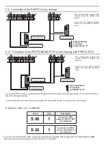
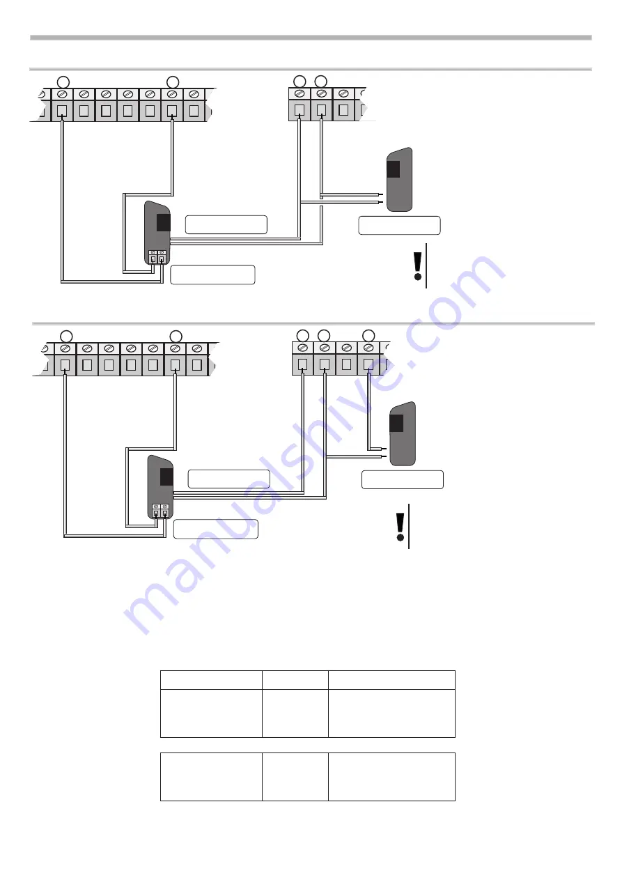
3.12 Connection of the PHOTO A (only closing)
2 3 4 5 6 7 8 9 10
POWER SUPPLY OF
THE PHOTO-BEAM
13 14 15 16
+
-
Photo-beam receivers.
N.C. terminal board.
POWER SUPPLY OF
THE PHOTO-BEAM
If the input FOTO
is not used,
put the S16 at “ 0”
The normally closed contact of the
receiver should be isolated from
tension.
If you you more couples of photo-
beams the connection should be
serial.
3.13 Connection of the PHOTO-BEAM FOTO A (only closing) with PHOTO-TEST
2 3 4 5 6 7 8 9 10
POWER SUPPLY OF
THE PHOTO-BEAM
13 14 15 16 17
+
-
Photo-beam receivers.
N.C. terminal board
POWER SUPPLY OF
THE PHOTO-BEAM
The normally closet contact of the
receiver should be isolated from
tensions.
If you you more couples of photo-
beams the connection should be
serial.
-
The PHOTO-TEST check the right working of the gate if the photo-beams are working properly. The control unit will do a
test before the gate opening.
In case the photo-beams are not working properly, the lamp will be turned on and the gate is not working.
If the input FOTO
is not used,
put the S16 at “0”
Set up
Value
Description
S 06
1
Activate the TEST
output for INPUT TEST
(Val. Default 0)
S 22
1
To activate the TEST
put at 1 the PHOTO A
(Val. Default 0)
To activate
the
TEST
put at
1
the
PHOTO A:
If you don’t need the PHOTO-TEST, connect the photo-beams
(see Par. 3.2)
and put at
0
in the function
S22
and
S06
(S06 should be deactivated only when other TEST are not available)
+
-
+
-
+
-
+
-
Summary of Contents for START S10
Page 21: ...NOTE 21 ...
Page 22: ...NOTE 22 ...
Page 45: ...NOTE 21 ...
Page 46: ...NOTE 22 ...
Page 67: ...NOTE 19 ...
Page 89: ...NOTE 21 ...
Page 90: ...NOTE 22 ...
Page 113: ...NOTE 21 ...
Page 114: ...NOTE 22 ...

