5. External connections
5.8 XV300 Touch Panel as a SmartWire-DT® coordinator
wiring
l
When connecting the SmartWire-DT® network to the SmartWire-DT interface,
make sure to only use the following ribbon cables:
SWD4-100LF8-24 with the corresponding SWD4-8MF2 blade terminals OR
SWD4-(3/5/10)F8-24-2S (prefabricated cable)
5.8.2.1 Commissioning the SmartWire-DT
®
network
The following requirements must be met before switching on the network after initial
commissioning, replacement, or modifying the SmartWire-DT® configuration:
l
All SWD modules must be connected to each other via SmartWire-DT® cables.
l
The SmartWire-DT® network must be connected to the SmartWire-DT interface.
l
The power supply for the device and for SmartWire-DT® must be on and connected.
l
The SmartWire-DT® master's POW LED must be lit up with a solid light.
l
The status LEDs of the connected SWD modules must be flashing or showing a solid
light.
l
There must be a PLC project in which the SmartWire-DT master is configured (pro-
ject configuration).
l
The PLC runtime system must be installed on the device.
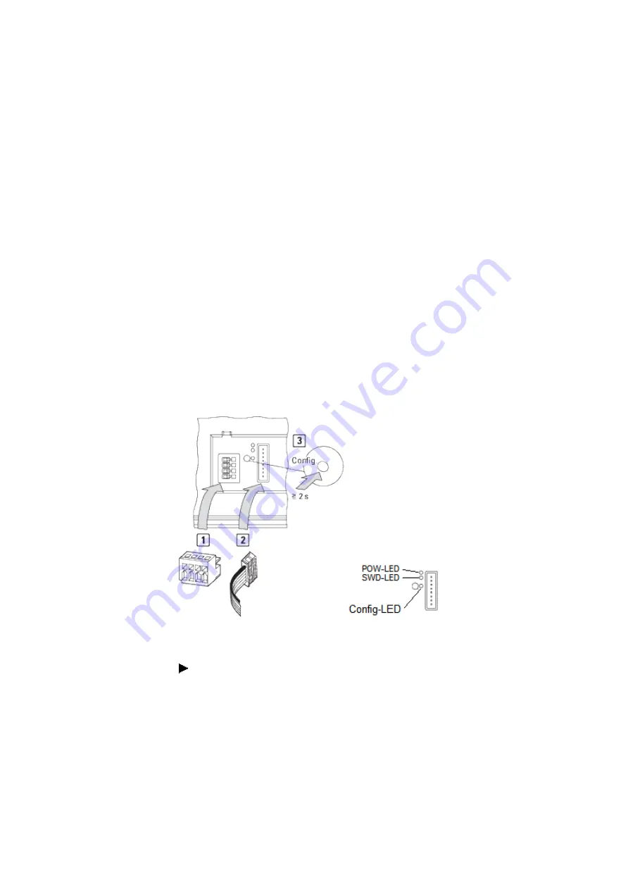
Figure 34: Commissioning SmartWire-DT® sequence
Perform the following instructions :
Press and hold down the Config button for at least 2 seconds.
The SmartWire-DT® master interface's SWD LED will start flashing with an orange
light.
The status LEDs of the connected SWD modules will start flashing.
The SmartWire-DT® master interface's SWD LED will start flashing with a green light.
All SWD modules are addressed.
The SmartWire-DT® network's physical configuration will be stored in the HMI panel's
non-volatile memory as the target configuration.
The SmartWire-DT® master interface's SWD LED will show a solid green light.
62
XV300
12/15 MN048017 EN www.eaton.eu


