

5 Implementation of EtherNet/IP
5.3 VSC-Vendor Specific Classes
92
XI/ON: XNE-GWBR-2ETH-IP
09/2011 MN05002007Z-EN
www.eaton.com
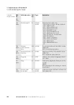
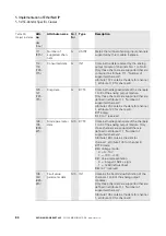
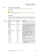
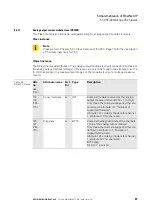
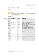
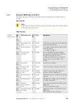
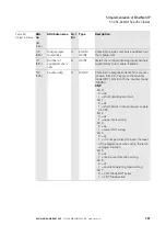
111
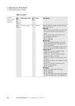
(6Fh)
Number of
supported chan-
nels
G
USINT
States the number of analog input channels
supported by this module Instance.
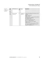
112 -
119
(70h -
77h)
Produced data
G
INT
Contains the data transmitted by the analog
input module of channels No. 1 to No. 8.
Only those channels are supported that are
contained in attribute 111, "Number of
supported channels".
Attribute 112 contains the data for channel
1, attribute 119 for channel 8.
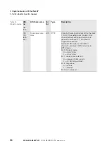
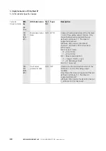
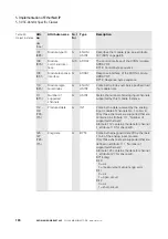
120 -
127
(78h -
7Fh)
Diag data
G
BYTE
Contains the diagnostic data of the channels
1 to 8 of the analog input module.
Only those channels are supported that are
defined in attribute 111, "Number of
supported channels".
Attribute 120 contains the data for channel
1, attribute 127 for channel 8.
BYTE diag:
Bit0:
0 =ok
1 =measurement value range error
Bit1 to 7: reserved
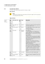
128 -
135
(80h -
87h)
Mode parameter
data
G/S
BYTE
Contains the diagnostic data of the channels
1 to 8 of the analog input module. Only
those channels are supported that are
defined in attribute 111, "Number of
supported channels".
Attribute 128 contains the data for
channel 1, attribute 135 for channel 8.
BYTE mode:
Bit0: Voltage mode:
0 =0…10V
1 =-10V…+10V
Bit 1: Value representation
0 =Integer (15Bit + sign)
1 =12Bit (left-justified)
Bit 2: Diagnostic:
0 = enable
1 = disable
Bit 3 to 7: reserved
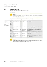
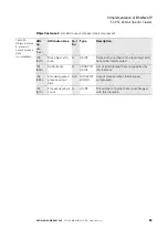
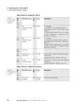
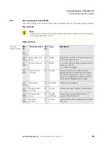
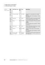
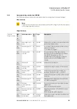
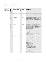
Table 49:
Object instance
Attr.
no.
dec.
(hex.)
Attribute name
G
et/
S
et
Type
Description


