4 Technical features
4.3 Technical data
XI/ON: XNE-GWBR-2ETH-IP
09/2011 MN05002007Z-EN
www.eaton.com
31
4.3.1
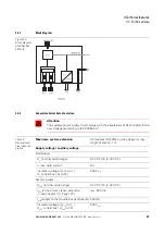
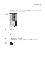
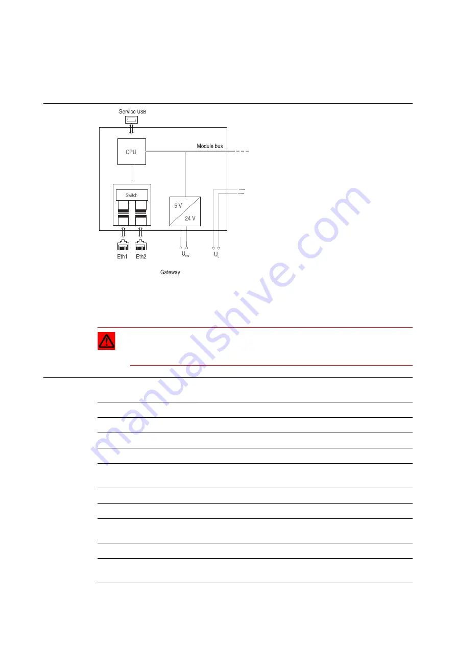
Block diagram
4.3.2
General technical data of a station
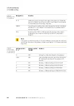
Figure 19:
Block diagram
XNE-GWBR-
2ETH-IP
Attention
The auxiliary power supply must comply with the stipulations of SELV (Safety Extra
Low Voltage) according to IEC 60364-4-41.
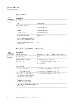
Table 2:
General tech-
nical data of a
station
Maximum system extension
32 modules (XN, XNE) in slice design or max.
length of station: 1 m
Supply voltage/ auxiliary voltage
Field supply
U
L
nominal value (range)
24 V DC (18 to 30 V DC)
I
L
max. field current
8 A
Insulation voltage (U
L
to U
SYS
/
U
L
to field bus / U
L
to FE)
500 V
rms
System supply
U
SYS
nominal value (range)
24 V DC (18 to 30 V DC)
I
SYS
(at maximum station extension
→
max.
600 mA
I
MB
(supply to the moudle bus participants) 400 mA
Insulation voltage (U
SYS
to U
L
/
U
SYS
to field bus / U
SYS
to FE)
500 V
rms

