5
Section II – Overhaul
A. Unit Removal
WARNING
Turn off all electrical power and relieve hydraulic
pressure. Block any load that could generate
pressure.
1. Remove the unit from the system.
2. Cap all system openings to prevent entry of dirt.
B. Special Tools
The following special tools are needed:
1. Torque wrench rated in lb.in.
2. Flushing plate. Refer to figure 6 for dimensions.
3. 0-500 milliammeter.
C. Improvised Tools
No improvised tools are required for overhaul.
D. Disassembly
Periodic maintenance of the valve will generally not require
disassembly to the extent described here. However, the
sequence can also be used as a guide for partial disassem-
bly. In general, disassembly is accomplished in the item
number sequence shown on Figure 1. Special procedures
are included in the following steps:
1. Thoroughly clean the exterior of the valve.
2. The valve is full of fluid, so hold it over a container
when the cover (3, Figure 1) is removed.
3. Remove parts (1) thru (11) according to sequence.
4. Remove the pilot stage parts (12) thru (26) as a unit
by pulling the adapter (26) from the main stage body (37); at
the same time, push the coil connector from the body. See
Figure 4. Disassemble the pilot stage according to numerical
sequence in Figure 1.
5. Remove parts (27) thru (37).
E. Cleaning
All parts must be thoroughly cleaned and kept clean during
inspection and assembly. The close tolerance of servo
valves makes this requirement more stringent than usual.
Use a commercial solvent which is compatible with the sys-
tem fluid to clean the parts. Compressed air may be used in
cleaning the valve but it must be filtered to remove water and
contamination. Clean compressed air is particularly useful in
cleaning the spool orifices and body passages.
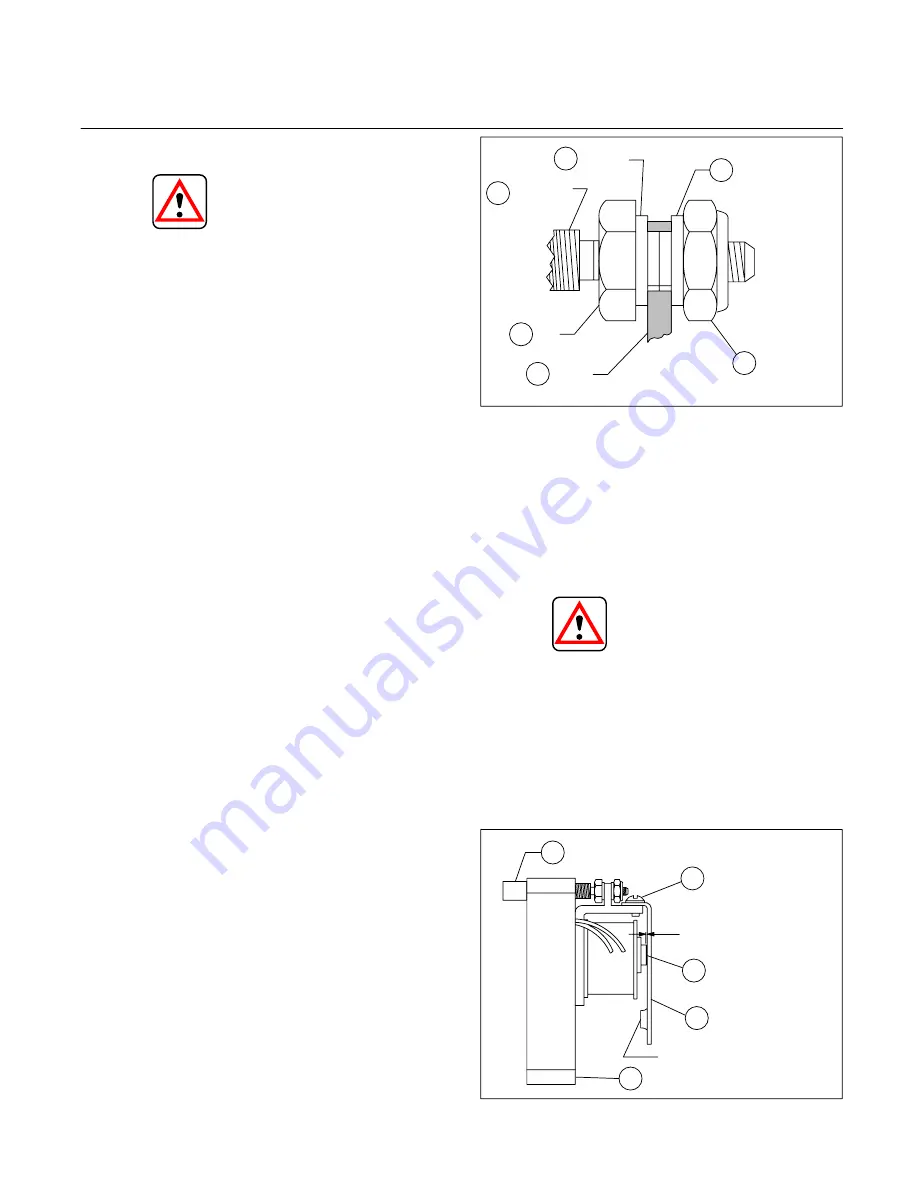
Figure 2. Locating of Adjustment Screw Nuts and Washers
19
18
22
24
23
25
Washer
Lock
Nut
Frame
Nut
Adjusting
Screw
Washer
F. Inspection, Repair, and
Replacement
Check that all internal passages are clean and unob-
structed. Examine all mating surfaces for nicks and burrs.
Check the condition of threaded parts and threaded holes.
Check the retaining ring (15). Minor burrs can be removed
with an India stone.
CAUTION
The spool (33) must not have the land edges broken
with the stone. They are held to a very close
tolerance.
1. Make sure that the 0.020 hole in the side of the spool
(33) and the 0.030 hole in the orifice plug which is screwed
in the end of the spool are completely open. (See Figure 5.)
The orifice plug in the end of the spool may have to be
removed to clean out contaminants that have gathered
inside the spool.
Figure 3. Pilot Stage Servo Valve Adjustment Locations
25
13
26
12
20
Adjusting Screw
Holding Screws
and Lockwashers
0.010 Clearance
Nozzle
Flapper Armature
Adapter S/A
Extrusion


