9
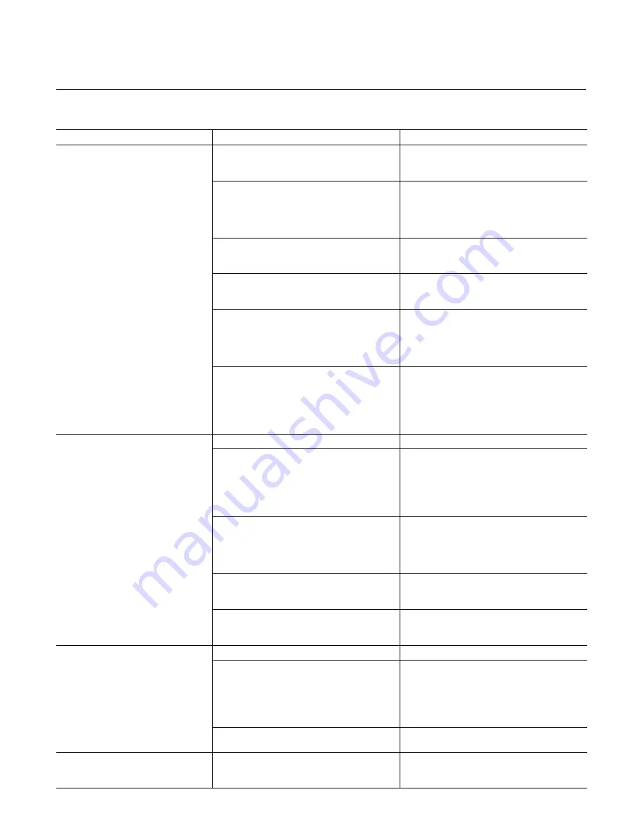
E. Troubleshooting
TROUBLE
PROBABLE CAUSE
REMEDY
No load movement
Insufficient control pressure or supply
pressure.
Check the control pressure or supply
pressure – the gage installation should be
close to the servo valve.
Improper or poor electrical connections.
With the amplifier or signal source turned
off, check continuity with an ohmmeter for
cold solder joints on the electrical
connectors, broken leads and for improper
pin wiring.
Flow ports blocked.
Check for proper manifolding (O-rings) and
for obstructions or improper piping of the
hydraulic lines.
Servo valve mounting bolts too tight.
Loosen the four servo valve mounting bolts
and adjust to the values specified in
Section VI – Overhaul.
Amplifier or signal source inoperative.
Install milliammeters between the torque
motor and amplifier or signal source, one in
series with line “A” and the other in series
with line “D”, and check for the proper dif-
ferential currents.
Torque motor inoperative.
With the amplifier or signal source turned
off, check the torque motor coils for either
an open or shorted condition by placing an
ohmmeter across pins “A” and “B” of the
electrical connector for one coil and across
pins “C” and “D” for the other.
Load movement in only one
di
ti
Pilot spool not centered.
Recenter pilot spool. Refer to page 8.
y
direction
One torque motor coil inoperative.
With the amplifier or signal source turned
off, check the torque motor coils for either
an open or shorted condition by placing an
ohmmeter across pins “A” and “B” of the
electrical connector for one coil and across
pins “C” and “D” for the other.
Improper or poor electrical conditions.
Install milliammeters between the torque
motor and amplifier or signal source, one in
series with line “A” and the other in series
with line “D”, and check for the proper dif-
ferential currents.
Insufficient control pressure.
Check the control pressure – the gage
installation should be close to the servo
valve.
Flow ports blocked.
Check for proper manifolding (O-rings) and
for obstructions or improper piping of the
hydraulic lines.
Movement of load in both
di
ti
b t
i
l
d
Pilot spool not centered.
Recenter pilot spool. Refer to page 8.
directions, but maximum load
movement obtainable in only one
direction.
Amplifier or signal source null shift.
Install milliammeters between the torque
motor and amplifier or signal source, one in
series with line “A” and the other in series
with line “D”, and check for the proper dif-
ferential currents. Refer to operating
characteristics.
Main sleeve too far out of adjustment.
Refer to spool centering adjustment page
8 then null adjustment page 7.
Erratic load movement
Contamination.
Install the proper filter required. Clean the
system components, and thoroughly flush
the system.


