


10
Type VFI, Fluid-insulated Switchgear
INSTALLATION, OPERATION AND MAINTENANCE INSTRUCTIONS
MN285006EN March 2018
Dissolved gas analysis
Dissolved gas analysis is a useful technique for diagnosing
abnormal conditions and assessing the “normal” condition
of insulating fluid in fluid-filled equipment. The method
employed is ASTM D3612, which is used in conjunction
with IEEE Std C57.104™-2008
I
EEE Guide for the Detection
and Determination of Generated Gases in Oil Immersed
Transformers and their Relations to the Serviceability of the
Equipment.
Table 4
provides recommendations on dissolved
gas levels in fluid insulated switchgear.
Table 2 . Test limits for service-aged fluid
Fluid Test
Method
Requirement
Dielectric Strength
Acid*
Dissipation*
Interfacial*
Water Content
D877
D974
D924
D971
D1533
26 kV minimum
0.20 mg KOH/g maximum
1.0% maximum
24 mN/m minimum
See
Table 3
*Requirements shown are for mineral oil only. Service-aged limits for ester
fluids have not been established at the time of this publishing.
Table 3 . Service recommendations for insulating fluid moisture contents
Fluid Type
Water Content (ppm)
Service Recommendation
Mineral Oil
< 25
Continue with Eaton recommended maintenance schedule (inspection and sampling every 2 years).
25 – 35
Obtain another fluid sample for moisture analysis in 6 months to determine if moisture levels are rising. Refer
to the
Fluid sampling guidelines
section in this manual. If moisture levels increase, determine leak
point and repair. Process or replace the fluid if water conent has exceeded 35 ppm.
> 35
De-energize the equipment immediately. Take another sample and verify results. If verified, process or replace
the fluid before returning to service.
FR3
< 400
Continue with Eaton recommended maintenance schedule (inspection and sampling every 2 years).
400 – 600
Obtain another fluid sample for moisture analysis in 6 months to determine if moisture levels are rising. Refer
to the
Fluid sampling guidelines
section in this manual. If moisture levels increase, determine leak
point and repair. Process or replace the fluid if water conent has exceeded 600 ppm.
> 600
De-energize the equipment immediately. Take another sample and verify results. If verified, process or replace
the fluid before returning to service.
E200
< 800
Continue with Eaton recommended maintenance schedule (inspection and sampling every 2 years).
800 – 1200
Obtain another fluid sample for moisture analysis in 6 months to determine if moisture levels are rising. Refer
to the
Fluid sampling guidelines
section in this manual. If moisture levels increase, determine leak
point and repair. Process or replace the fluid if water conent has exceeded 1200 ppm.
> 1200
De-energize the equipment immediately. Take another sample and verify results. If verified, process or replace
the fluid before returning to service.
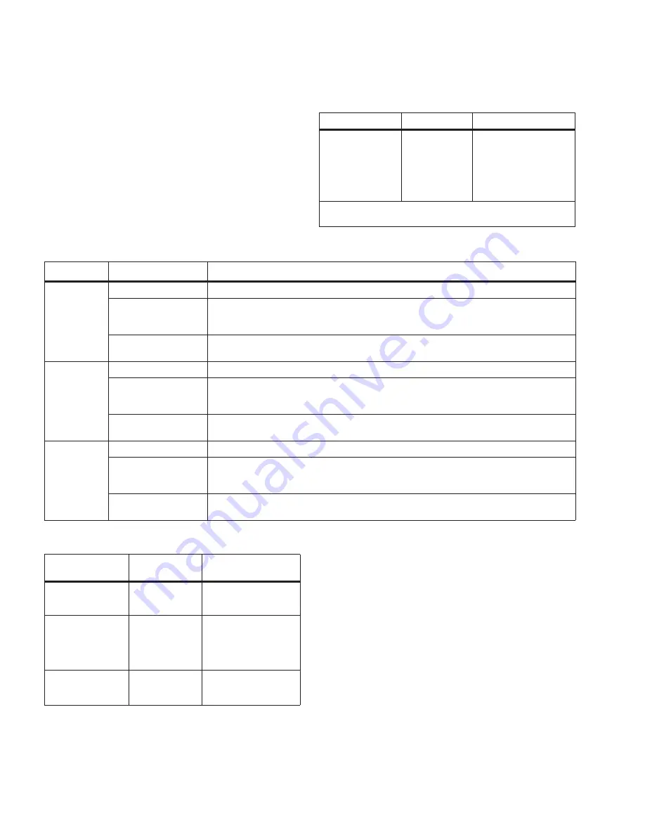
Table 4 . Dissolved gas in insulating fluid maintenance
chart
Acetylene Level
C2H2
Total Combustible
Gas
Required Action
Less than 35 ppm
Less than 500 ppm
Normal Level - Resample
per routine maintenance
schedule
35-50 ppm
500-1000 ppm
Caution Level - Resample
at 3-6 months to espablish
trend; maintain fluid if
gas levels increase to
hazardous level.
More than 50 ppm
More than 1000
ppm
Hazardous Level - Remove
unit from service and
maintain the fluid.
Replacement parts
Only factory-authorized replacement parts are to be used
for Eaton’s Cooper Power series Distribution Switchgear
products. Replacement parts are available through the
factory Service Department. To order replacement parts,
refer to the nameplate and provide the product type, serial
number, catalog number, voltage rating, and a description
of the part. Contact your Eaton representative for additional
information and ordering procedures. The following
documents are also available for common field repairs and
procedures:
●
MN285009EN – Cover gasket replacement, cover
instalation, leak check procedures and fluid sampling
porcedures.
●
MN285007EN – Visible break window replacement
procedure.


