background image

2

Section 1: Introduction

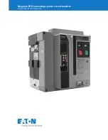
Series NRX with PXR – Type NF Low Voltage Power (Air) Circuit Breaker Instruction Manual

   MN013001EN   May 2015   www.eaton.com

The fixed configuration is designed for front/rear bus con-

nections .  The drawout version, in conjunction with its 

drawout cassette, is a through-the-door design having 

three breaker positions with the compartment door closed 

(CONNECT, TEST, DISCONNECT) and one position out of its 

compartment on extension rails (WITHDRAWN) . 

Product Labeling and Identification

The circuit breaker nameplate, located on the right side of 

the breaker, provides complete rating information and 

should always be inspected to ensure the information 

shown is in keeping with the product ordered (Figure 1) .  

Become familiar with the nameplate .

Figure 1 .  Series NRX Nameplate Location .

NAS6163W

Air Circuit Breaker

Frame
Type NF

1600 Ampere Frame

3 Pole

50/60 Hz

Interrupting Ratings

RMS Symetrical Ampere
Ue 

Icu kA 

Ics kA

240~ 85  50
440~ 85  50
690~ 42  42
Uimp 

8 kV Catagory B

Withstand Ratings

RMS Symetrical Ampere
Ue 

Icw kA (1 s)

240~ 42
440~ 42
690~ 42
Trip Unit Auxiliary Voltage = 24 Vm

Accessories

Motor Operator 

110-125 Vm

Spring Release 

110-127 V~, Vm

Latch Check Switch  NONE
Shunt Trip #1 

110-127 V~, Vm

Shunt Trip #2 

NONE

UVR NONE
Auxiliary Switch 

NONE

Bell Alarm Sw/OTS  NONE

P.O. #

G.O. #

Item #

Seq #

YYMMDD

Cat #

NAS6163WLNDABANENNDX

Enclosure Requirements

68D2555
Installation and Operating
Instructions
MN013001EN

WARNING 

Series nrx circuit breakers should not, under any cir-

cumstances, be applied outside their nameplate ratings .  

Operation outside of these ratings could result in death, 

bodily injury, or property damage .

Summary of Contents for Series NRX

Page 1: ...aker Instruction Manual Instruction Manual MN013001EN Instructions Apply to Type NF Frame Series NRX ANSI UL1066 UL489 IEC IZMX16 Typical Drawout Circuit Breaker and Cassette Typical Fixed Circuit Bre...

Page 2: ...the Drawout Circuit Breaker 14 Rejection Interlocks 15 Circuit Breaker Positioning 15 Installing Fixed Circuit Breaker 17 Operating Mechanism 18 SECTION 3 BREAKER GENERAL OPERATION CIRCUIT BREAKER DES...

Page 3: ...lease SR 25 Latch Check Switch LCS 25 Motor Operator 25 Mechanical Devices 25 SECTION 5 DIMENSIONAL DRAWINGS FOR INSTALLATION OF DRAWOUT CIRCUIT BREAKERS 27 SECTION 6 DIMENSIONAL DRAWINGS FOR INSTALLA...

Page 4: ...ply could result in the cassette tipping for ward resulting in equipment damage and or bodily injury CAUTION Do not store equipment on its back This could result in equipment damage CAUTION It is impo...

Page 5: ...nce of this equipment the following prac tices must be followed 1 Only qualified electrical personnel familiar with the equipment its operation and the associated hazards should be permitted to work o...

Page 6: ...Figure 1 Become familiar with the nameplate Figure 1 Series NRX Nameplate Location NAS6163W Air Circuit Breaker Frame Type NF 1600 Ampere Frame 3 Pole 50 60 Hz Interrupting Ratings RMS Symetrical Amp...

Page 7: ...Hz capability LSI ZSI W Modbus 2Q LSI ZSI W Modbus ARMS 2R LSIG A ZSI W Modbus 2S LSIG A ZSI W Modbus ARMS 2T LSI ZSI W Modbus 2V LSI ZSI W Modbus ARMS 2W LSIG A ZSI W Modbus 2X LSIG A ZSI W Modbus AR...

Page 8: ...ond Shunt Trip N None A 110 125 Vac dc UVR R 208 240 Vac dc UVR L 24 Vdc UVR H 48 Vdc UVR S 60 Vdc UVR 1 110 127 Vac dc Second Shunt Trip 2 208 240 Vac dc Second Shunt Trip 4 24 Vdc Second Shunt Trip...

Page 9: ...Metal Counter Provided 5 PB Covers Metal Metal Safe Off No Counter 6 PB Covers Metal Metal Safe Off Counter Provided Position 19 Drawout Breaker Shipping Fixed Breaker Terminals Door Frame Kit D Drawo...

Page 10: ...es including primary and secondary connections Standard flat terminal pads on the rear of the cassette provide for a variety of primary connection configurations Optional primary adapters are availabl...

Page 11: ...www eaton com Figure 3 Typical NRX Type NF Drawout Circuit Breaker Front and Rear Views Note N Refer to Figure 6 for more visual details of front cover 1 Arc Chute Cover 2 Primary Shroud 3 Lifting Ha...

Page 12: ...d Rear Views 1 Drawout Extension Rail 2 Stationary Primary Contacts 3 Interlock Plate Pins 4 Grounding Earthing Bar 5 Safety Shutters Open 6 Hand Lifting Indentation 7 Gas Ventilation Opening 8 Second...

Page 13: ...e NF Fixed Circuit Breaker Rear Connected Type Note N Refer to Figure 6 for more visual details of front cover 1 Arc Hood Baffle 2 Arc Hood 3 Secondary Contacts 4 Front Cover 5 Secondary Wiring Contac...

Page 14: ...4 Nameplate 5 Manual ON 6 Operations Counter 7 Position Indicator 8 Levering Access Door 9 Frame Rating Module 10 FRM Battery Cover 11 Manual OFF 12 USB and Aux Power Ports 13 Pop out Trip Flag 14 Tr...

Page 15: ...at top of indicator is partially full or totally full of blue beads Transport was not in keeping with instructions breaker con tainer was tilted or overturned Check breaker closely for dam age Triang...

Reviews: