OPERATING INSTRUCTIONS
Eaton 9390 UPS, 9395 UPS, and 9395 SSBM Sync Control Installation and Operation Manual
S
P-164000052 Rev 2
www.eaton.com/powerquality
4-4
1
2
3
4
5
6
7
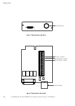
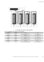
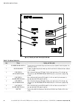
Figure 4‐3. Eaton Sync Control Controls and Indicators
Table 4‐1. Controls and Indicators
Item
Name
Function and Description
1
PREFERRED SOURCE SELECTOR
Two‐position rotary switch allowing either of the two system load buses to be assigned as the
master sync source.
2
LOAD SYNC ENABLE
Enables or disables the automatic Eaton Sync Control unit. Switch is illuminated when load sync
action is enabled.
3
UPS SYSTEM-A
ACTIVE MASTER SOURCE
When illuminated, indicates UPS System-A is the active master source. This indicator may
illuminate even if the PREFERRED SOURCE SELECTOR switch is not set to the corresponding
position.
4
UPS SYSTEM-A
SYNCHRONIZED TO LOAD-B
When illuminated, indicates that UPS System-A is in the non-master system mode and is
synchronized to the UPS System-B load bus.
5
UPS SYSTEM-B
ACTIVE MASTER SOURCE
When illuminated, indicates UPS System-B is the active master source. This indicator may
illuminate even if the PREFERRED SOURCE SELECTOR switch is not set to the corresponding
position.
6
UPS SYSTEM-B
SYNCHRONIZED TO LOAD-A
When illuminated, indicates that UPS System-B is in the non-master system mode and is
synchronized to the UPS System-A load bus.
7
LAMP TEST
Pressing the pushbutton illuminates all indicators on the Eaton Sync Control unit for visual
testing.

