background image

WARRANTY

Eaton 9390 UPS, 9395 UPS, and 9395 SSBM Sync Control Installation and Operation Manual  

S

  P-164000052 Rev 2

 www.eaton.com/powerquality

5-2

This page intentionally left blank.

Summary of Contents for Powerware 9390

Page 1: ...Eaton Powerware 9390 160 N 4x0 Sync Control Ea https eaton power ru catalog eaton 9390 9390 160 n 4x0...

Page 2: ...Eaton 9390 UPS 9395 UPS and 9395 SSBM Sync Control Installation and Operation Manual Sync Control Installation and Operation Manual...

Page 3: ......

Page 4: ...Eaton 9390 UPS 9395 UPS and 9395 SSBM Sync Control Installation and Operation Manual Sync Control Installation and Operation Manual...

Page 5: ...et de maintenance des batteries et de l onduleur Veuillez consulter enti rement ces instructions avant de faire fonctionner l quipement et conserver ce manuel afin de pouvoir vous y reporter ult rieur...

Page 6: ...ng the Site 2 1 2 2 1 Environmental and Installation Considerations 2 1 2 2 2 Eaton Sync Control Wiring Preparation 2 4 2 3 Inspecting and Unpacking the Eaton Sync Control 2 4 3 Installation 3 1 3 1 I...

Page 7: ...rol 3 10 Figure 3 8 Eaton 9395 UPS and Plus 1 UPS 450 550 kVA Interface Locations for Eaton Sync Control 3 11 Figure 3 9 Eaton 9395 UPS and Plus 1 UPS 650 825 kVA Interface Locations for Eaton Sync Co...

Page 8: ...transfer of the load from one load bus to another by means of downstream dual source solid state transfer switches Without the load sync option the two system output critical load buses could become o...

Page 9: ...a command or option that you type or enter at a prompt S Italic type highlights notes and new terms where they are defined S Screen type represents information that appears on the screen or LCD Icon D...

Page 10: ...inside the UPS or SBM WARNING S The UPS system contains its own energy source batteries The output terminals may carry live voltage even when the UPS is disconnected from an AC source S To reduce the...

Page 11: ...scribe S UPS or SBM cabinet optional components and accessory installation instructions including site preparation planning for installation and wiring and safety information Detailed illustrations of...

Page 12: ...offered as part of the sales contract for the UPS Contact service in advance usually a two week notice is required to reserve a preferred startup date 2 2 Preparing the Site For the Eaton Sync Contro...

Page 13: ...ol Installation and Operation Manual S P 164000052 Rev 2 www eaton com powerquality 2 2 FRONT VIEW 66 27 26 09 Dimensions are in millimeters inches 61 18 24 09 Four Mounting Holes in Rear of Panel 3 1...

Page 14: ...rol Installation and Operation Manual S P 164000052 Rev 2 www eaton com powerquality 2 3 LEFT SIDE VIEW RIGHT SIDE VIEW Knockout Holes for 1 Inch Conduit Dimensions are in millimeters inches 20 32 8 0...

Page 15: ...m 30 to 600V The wire should be rated at 600V 1A minimum and 12 AWG maximum S Sync Control dry contacts are rated at 250 Vac Vdc at 6A per contact maximum load S When installing external wiring betwee...

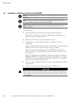
Page 16: ...1 Installation and Wiring with an Eaton 9390 UPS NOTE When installing wiring connections conduit must be installed between the Eaton Sync Control and the UPS cabinet To install and wire 1 Install the...

Page 17: ...e from another model UPS to an Eaton 9390 UPS using the Eaton Sync Control accessory use Phase A Phase B and Neutral connections from the other UPS DO NOT connect the other model UPS Phase C bypass an...

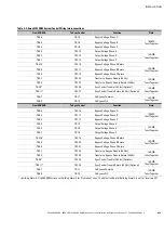
Page 18: ...ss NO OR J2 5 Industrial Relay Card TB1 1 On Bypass Common 14 AWG Twist Together J2 6 Industrial Relay Card TB1 2 On Bypass NO From UPS System B To Sync Control Function Note TB6 1 TB1 10 Bypass Volta...

Page 19: ...ut Voltage Phase A UPS System A Output Voltage Phase B UPS System A Output Voltage Neutral or Phase C for SBM UPS System B Output Voltage Phase A UPS System B Output Voltage Phase B UPS System B Outpu...

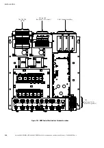
Page 20: ...9395 UPS and 9395 SSBM Sync Control Installation and Operation Manual S P 164000052 Rev 2 3 5 TB1 TB2 TB6 Mini CSB Building Alarm Terminal Block P5 Figure 3 3 Eaton 9390 UPS 40 80 kVA Interface Locat...

Page 21: ...9395 UPS and 9395 SSBM Sync Control Installation and Operation Manual S P 164000052 Rev 2 3 6 TB6 TB1 TB2 Mini CSB Building Alarm Terminal Block P5 Figure 3 4 Eaton 9390 UPS 100 160 kVA Interface Loca...

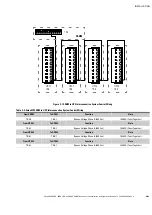
Page 22: ...Bypass Voltage Phase B Output Voltage Phase A Output Voltage Phase B Output Voltage Neutral Bypass Voltage Return Phase B TB6 Figure 3 5 TB6 Terminal Block Detail 1 8 P5 BUILDING ALARM 3 BUILDING ALA...

Page 23: ...locations and assignments termination requirements conduit landing locations and terminal access instructions NOTE Completethe wiring to the X Slot Relay Interface Card or Industrial Relay Card termin...

Page 24: ...ss NO OR J2 5 Industrial Relay Card TB1 1 On Bypass Common 14 AWG Twist Together J2 6 Industrial Relay Card TB1 2 On Bypass NO From UPS System B To Sync Control Function Note TB6 1 TB1 10 Bypass Volta...

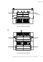
Page 25: ...164000052 Rev 2 3 10 TB3 TB6 NOTE Interface connections are located in the same positions on the 9395 550 275 UPS 225 550 kVA and the 9395 UPS 300 kVA X Slot Communication Bays Install Relay Interface...

Page 26: ...S P 164000052 Rev 2 3 11 TB3 TB6 NOTE Interface connections are located in the same positions on the 9395 Plus 1 UPS 225 275 kVA X Slot Communication Bays Install Relay Interface Card in any open bay...

Page 27: ...Control Installation and Operation Manual S P 164000052 Rev 2 3 12 TB3 TB6 X Slot Communication Bays Install Relay Interface Card in any open bay ISBM SECTION Figure 3 9 Eaton 9395 UPS and Plus 1 UPS...

Page 28: ...M Sync Control Installation and Operation Manual S P 164000052 Rev 2 3 13 TB3 TB6 X Slot Communication Bays Install Relay Interface Card in any open bay ISBM SECTION Figure 3 10 Eaton 9395 UPS 1000 11...

Page 29: ...llation and Operation Manual S P 164000052 Rev 2 3 14 Strain Relief Bushing Figure 3 11 Relay Interface Card End View 1 15 K4 Normally Open On Bypass 6 4 K4 Common On Bypass Strain Relief Bushing 5 K4...

Page 30: ...lock J2 from Relay Contacts to Customer s Monitoring Equipment Figure 3 13 Industrial Relay Card Table 3 3 IRC Wire Terminations IRC Terminal Function Remarks J2 1 NC Normal Mode J2 2 COM J2 3 NO J2 4...

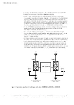
Page 31: ...for wiring requirements Figure 3 1 shows the Eaton Sync Control TB1 terminal block and ground terminal locations Figure 3 2 shows the TB1 terminal block wiring detail Figure 3 14 shows the typical lo...

Page 32: ...7 Sync Control Trouble Return 24 Vdc Optional TB4 7 TB1 1 On Bypass Common 14 AWG Twist Together TB4 8 TB1 2 On Bypass NO From SSBM B To Sync Control Function Note TB3 6 TB1 10 Bypass Voltage Phase A...

Page 33: ...Control Installation and Operation Manual S P 164000052 Rev 2 3 18 X Slot Communication Bays TB1 and TB2 See Figure 3 15 for detail TB4 TB5 TB6 and TB7 TB3 See Figure 3 18 for terminal assignments Fi...

Page 34: ...M Sync Control Installation and Operation Manual S P 164000052 Rev 2 3 19 TB1 TB2 See Figure 3 17 for terminal assignments Figure 3 15 TB1 and TB2 Interface Terminal Detail TB4 TB5 TB6 TB7 On Bypass F...

Page 35: ...All building alarm inputs require an isolated normally open or normally closed contact or switch rated at 24 Vdc 20 mA minimum connected between the alarm input and common terminal as shown Building...

Page 36: ...95 SBM to UPS Interconnection System Control Wiring From SSBM To UPS 1 Function Note TB3 9 TB6 1 Bypass Voltage Phase B 480 Vac 14 AWG Twist Together From UPS 1 To UPS 2 Function Note TB6 1 TB6 1 Bypa...

Page 37: ...INSTALLATION Eaton 9390 UPS 9395 UPS and 9395 SSBM Sync Control Installation and Operation Manual S P 164000052 Rev 2 3 22 This page intentionally left blank...

Page 38: ...onization reference to each system Each system uses this reference to regulate the inverter phase relationship so that the two system outputs can maintain synchronization with each other To establish...

Page 39: ...egardless of the position of the PREFERRED SOURCE SELECTOR switch S Dual redundant logic power supplies are incorporated within the Eaton Sync Control ensuring both systems remain synchronized even du...

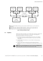
Page 40: ...n the non master system mode NOTE At any given time only one of the UPS systems can be in the non master system mode Figure 4 2 Synchronization Reference Control 4 3 Operation Perform the following pr...

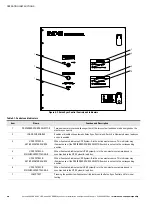
Page 41: ...cates UPS System A is the active master source This indicator may illuminate even if the PREFERRED SOURCE SELECTOR switch is not set to the corresponding position 4 UPS SYSTEM A SYNCHRONIZED TO LOAD B...

Page 42: ...ONIZED TO LOAD indicator illuminates for the non master system 5 To disable the automatic synchronization control press the LOAD SYNC ENABLE pushbutton and verify that the indicators including the LOA...

Page 43: ...OPERATING INSTRUCTIONS Eaton 9390 UPS 9395 UPS and 9395 SSBM Sync Control Installation and Operation Manual S P 164000052 Rev 2 www eaton com powerquality 4 6 This page intentionally left blank...

Page 44: ...erforms startup and commissioning of the Product b if the Product is moved to a new location by someone other than an authorized Eaton Customer Service Engineer in the USA or Agent outside of the USA...

Page 45: ...WARRANTY Eaton 9390 UPS 9395 UPS and 9395 SSBM Sync Control Installation and Operation Manual S P 164000052 Rev 2 www eaton com powerquality 5 2 This page intentionally left blank...

Page 46: ......

Page 47: ...P 1640000522 P 164000052 2...

Reviews: