INSTALLATION
EATON
Powerware
®
5125 (9910-E65) UPS Installation Guide for IBM
®
Applications
S
164201698 Rev 1
20
NOTE
The redundant power source must be protected with Transient Voltage Surge
Suppression (TVSS).
2.
Plug the equipment to be protected into the appropriate UPS output
receptacles (see page 25 for more information on load segments).
Table 7. Plug Types Supported
IBM Plug Type
Description
Quantity Supported
12
NEMA L6-30P
1
—
IEC 320-C14
4
—
IEC 320-C20
4
NOTE
DO NOT protect laser printers with the UPS because of the exceptionally high
power requirements of the heating elements.
NOTE
To prevent an overload alarm, verify that the total equipment ratings do not exceed
the UPS capacity.
3.
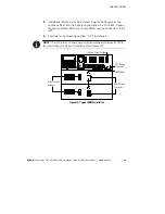
Verify that all load segment circuit breakers are in the ON position.
4.
Remove the breaker tie from all battery circuit breakers.
5.
Switch all battery circuit breakers to the ON position.
6.
Plug the UPS power cord into a power outlet.
The
μ
indicator flashes, indicating the UPS is in Standby mode
with the equipment offline.
7.
Press and hold the On
button for approximately three seconds.
The
μ
indicator illuminates solid and the load level indicators
display the percentage of load being applied to the UPS. The UPS is
now in Normal mode and supplying power to your equipment.
If the alarm beeps or a UPS alarm indicator stays on, refer to
“Troubleshooting” in the
Powerware 5125 Rack-Mount UPS
(5000/6000 VA) User’s Guide
.
The UPS automatically sets the output voltage based on the input
voltage. To change the output voltage, see “Configuration Mode”
on page 30.

