System assembly
Power Xpert
®
UX with W-VACi circuit breaker 6063308 G01 01 14 July 2011 www.eaton.com
33
3.4
Busbar coupling
3.4.1
Main busbar
General
The main busbar system is located in the top
compartment of the panel which is named as busbar
compartment.
Main busbars - coupling
1. Remove any oxide film from the mating surfaces of
the busbars and connecting strips with the use of very
fine abrasive cloth (eg Scotch Brite).
2. Hold the busbars in position as shown in the
illustration.
3. Place bolts, washers and nuts through bus bars as
shown in the illustration
4. Tighten the bolts by hand (use no tools).
5. Align the busbars and tighten the bolts.
Apply a torque of 40 Nm (M12 bolts).
6. Cover the joint with the insulation box using either
cable ties or plastic rivets to close the insulation
cover.
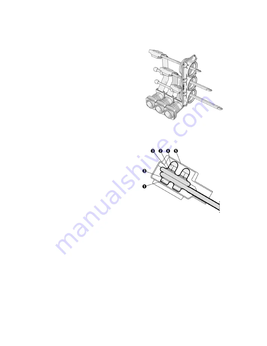
Fig. 3-6 Main busbar
Fig. 3-7 Bolts connection for main busbar
1. Bolt M12
2. Spring washer 12
3. Plain washer 12
4. Cover nut M12
5. Cover insulation


