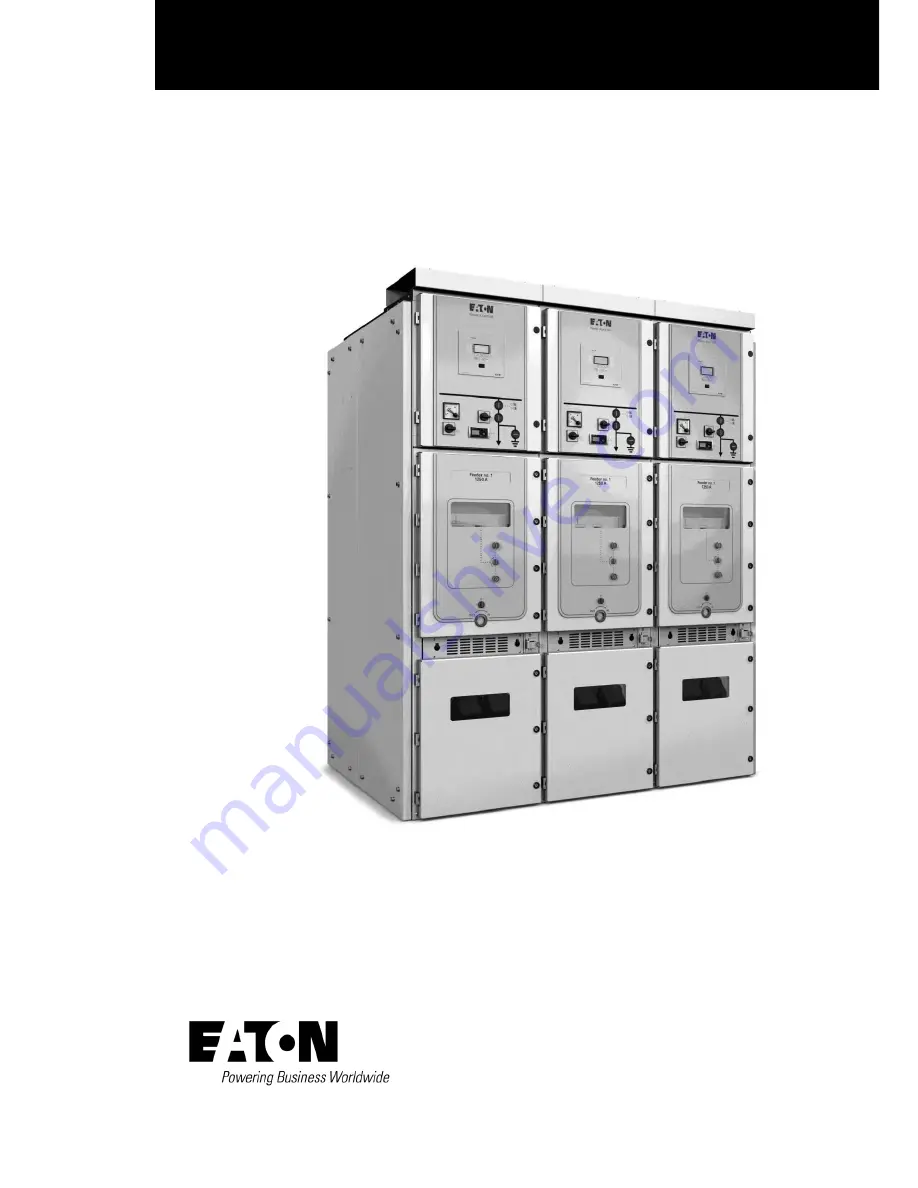
User manual Power Xpert
®
UX
Power Xpert
UX with W-VAC
i
circuit breaker (up to 24 kV)
Air Insulated Medium-voltage switchgear
Page 1: ...User manual Power Xpert UX Power Xpert UX with W VACi circuit breaker up to 24 kV Air Insulated Medium voltage switchgear ...
Page 2: ...Table of contents Power Xpert UX with W VACi circuit breaker 6063308 G01 01 14 July 2011 www eaton com 2 ...
Page 3: ...itions 14 2 1 4 Cable connections 14 2 1 5 Voltage transformers 15 2 1 6 Current transformers 15 2 1 7 Auxiliary equipment 15 2 1 8 Earthing 16 2 1 9 Withdrawable units 17 2 1 10 Interlocks 18 2 2 Panel types 18 2 2 1 Circuit breaker panel 18 2 2 2 Bus section panel connecting panel 19 2 2 3 Incoming panel 20 2 2 4 Outgoing panel 20 2 2 5 Metering panel 20 2 2 6 Contactor panel 20 2 3 Equipment sa...
Page 4: ...39 4 1 3 Mechanical operation door closed 40 4 1 4 Electrical operation 40 4 2 Unit insertion and withdrawal 41 4 2 1 Standard interlocking 41 4 2 2 Inserting a unit 42 4 2 3 Door interlock mechanism 43 4 2 4 Withdrawing a unit 43 4 2 5 Locking the shutters 44 4 3 Earthing 45 4 3 1 Cable door interlock mechanism 45 4 3 3 Switching on off the earthing switch 46 4 3 4 Earthing busbar cable using wit...
Page 5: ...ton com 5 7 Accessories 55 7 1 List of available accessories 55 7 1 1 Power Xpert UX 55 7 1 2 Optional 55 8 Glossary 56 8 1 Safety and qualification of personnel 56 8 2 Abnormal operating conditions 56 8 3 Equipment and the area around it 57 9 Appendix 58 9 1 General 58 9 2 Floor Plan drawings 59 ...
Page 6: ...anel function and the rated current of the panel in question determine the width of the panel Options The installation may be provided with optional equipment such as busbar insulating bushings voltage transformers etc The standard installation supplied is a single busbar model For further details see technical data 1 2 Using the manual 1 2 1 Target group The switchgear is designed for use by pers...
Page 7: ... manual but not explained further Chapter 9 Appendix This chapter shows the structure of all the documentation supplied with the system 1 3 Safety instructions Read this user manual carefully before commissioning the switchgear Make sure that you have read and understood all safety warnings and instructions 1 3 1 General instructions Eaton has done its utmost to inform user as accurately and as fu...
Page 8: ...m in which the switchgear has been set up and must meet at least the following requirements Clear space NOTE Operations not included in the manual must be carried out by or under the supervision of Eaton Front Access If the switchgear is arranged for Front cable access then rear or side clear space of at least 0 1 m is required However Eaton recommends at least 1 m at one end of the switchgear and...
Page 9: ...Ci circuit breaker 6063308 G01 01 14 July 2011 www eaton com 9 Clear space for Power Xpert UX switchgear with front and rear access Clear space for Power Xpert UX switchgear with front access Fig 1 1 Clear space for 12 kV and 17 5 kV panel ...
Page 10: ...ith W VACi circuit breaker 6063308 G01 01 14 July 2011 www eaton com Clear space for Power Xpert UX switchgear with front and rear access Clear space for Power Xpert UX switchgear with front access Fig 1 2 Clear space for 24 kV panel ...
Page 11: ... stored in the switch room Flammable materials combustible gases and dangerous chemicals must not be stored Availability of extinguishers Suitable extinguishers must be present in and around the switch room Obtain expert advice fire brigade on the best choice and location of the extinguishers 1 3 3 What to do in the event of a fire In the event of a fire in the switch room proceed as follows Evacu...
Page 12: ...ontains and the components used determine the complete product rating plate Each panel contains a complete product rating plate This also applies to the withdrawable part i e circuit breaker or contactor unit Fig 1 3 shows one example of product rating plate of the fixed part For the product rating plate on the withdrawable part refer to the manual of the withdrawable part i e circuit breaker or c...
Page 13: ...rtmented according to the type of function The compartments are I Low voltage compartment II Busbar compartment III Circuit breaker Contactor compartment IV Cable compartment 2 1 2 Circuit Breaker or Contactor unit The unit is inserted into the panel with the aid of a transport trolley Through the rollers on the carriage the unit is earthed when it is inserted Connection to the busbar system is es...
Page 14: ...nd The 58 pole secondary plug is connected control over the operation of the unit is now possible The compartment door can be opened Service position The unit is put placed in the service position when The unit is fully inserted and engaged into the compartment The primary contacts are connected and The 58 pole secondary plug is connected The compartment door cannot be opened In emergency situatio...
Page 15: ... rear of the cable compartment or in the riser sectionaliser panel Standard version At the cable connection points for the feeder panels or supply panels Customer specific version In the riser or bus section panel 2 1 7 Auxiliary equipment Auxiliary equipment such as relays position indicators meters and instruments are housed in the low voltage compartment of each switch panel Measuring and indic...
Page 16: ...tactor An optional LED flag indicator can also be mounted as part of the mimic diagram to indicate the On Off status of the earth switch Measuring An optional Ammeter Voltmeter and phase selector switch can be mounted in the LV compartment to provide current Voltage measurement for the circuit Additional multi function measuring meters can also be fitted 2 1 8 Earthing Power Xpert UX switchgear of...
Page 17: ...This assembly is mounted on a switch cradle and racking mechanism Electrical control signals are supplied from the low voltage compartment via a 58 pole secondary plug Mechanical and electrical interlocks prevent unintentional switching Refer to separate Operations and Maintenance Manual for the Circuit Breaker Withdrawble contactor unit The vacuum contactor is ideal for controlling applications r...
Page 18: ...irable switching operations For further information please see par 4 3 2 2 2 Panel types All Power Xpert UX switchgear is constructed in modular fashion with a series of panels with different functions Each panel is made up of 4 compartments Below is a summary of the types of panels fitted as standard in Power Xpert switchgear It is possible that they are not all included in any particular install...
Page 19: ... UX has designs that allow for the bus section to be mounted either on the Left or the Right of the riser panel An additional option with Power Xpert UX Switchgear is that the bus riser panel can be supplied suitably equipped with a number of units Circuit Breaker Contactor Earthing Truck Voltage Transformer Disconnect Isolation Bus sectionaliser Bus Riser A Sectionaliser panel B Riser panel right...
Page 20: ...d in this manual Operating or maintenance actions not described in this manual may be required Actions which are specific to a particular installation are described in the operating instructions supplied with it See the information pack which includes this manual Actions which are not described at all must only be carried out in consultation with an Eaton specialist The instructions of this specia...
Page 21: ...the working area Make sure that the installation is clean and dry check for leakage paths where voltage could track to the outside Fit earthing to the panel which is being worked on only operate on earthed panels Always check that the part that is being worked on is dead Working on a dead installation Fit earthing work on earthed panels only Always check that the system is dead When re commissioni...
Page 22: ...0 2000 2500 3150 4000 FC 800 1250 2000 2500 Rated short time withstand current kA s 25 3 26 3 3 31 5 3 40 3 50 3 20 3 25 3 Rated peak withstand current kA 63 80 100 125 50 63 Circuit breaker type W VACi IEC 62271 100 Rated nominal current A 630 1250 2000 3150 800 1250 2000 2500 Rated voltage kV 17 5 24 Rated breaking current kA 25 26 3 31 5 40 50 20 25 Rated short circuit making current kA 63 80 1...
Page 23: ...nvironment In accordance with IEC 62271 1 par 2 1 1 2 4 3 Dimensions and weights Main dimensions standard model Circuit breaker panel Depth Width C Height A Height including arc chamber B 12 kV and 17 5 kV UX17 25 kA 630 A 600 mm wide 1310 mm 600 mm 2200 mm 2760 mm UX17 31 5 kA 1250 A 600 mm wide 1310 mm 600 mm 2200 mm 2760 mm UX17 40 kA 2000 A 800 mm wide 1325 mm 800 mm 2200 mm 2760 mm UX17 40 50...
Page 24: ...630 A 600 mm wide 860 kg UX17 31 5 kA 1250 A 600 mm wide 880 kg UX17 40 kA 2000 A 800 mm wide 1230 kg UX17 40 kA 2000 A 800 mm wide 1650 kg UX17 50 kA 2000 A 800 mm wide 1650 kg UX17 40 kA 3150 A 1000 mm wide 1650 kg UX17 50 kA 3150 A 1000 mm wide 1650 kg 24kV UX24 20 kA 800 A 800 mm wide 1460 kg UX24 25 kA 1250 A 800 mm wide 1480 kg UX24 25 kA 2000 A 1000 mm wide 1820 kg UX24 25 kA 2500 A 1000 mm...
Page 25: ...or later extension of the installation or the addition of auxiliary equipment 3 1 3 Floor The floor of the operating area should comply with the following The floor must be flat and level to within 2mm per metre length of the intallation The floor must not have any raised areas bumps though indentations are permitted The floor must be of adequate strength Sections or foundation frames set in the f...
Page 26: ...ear access Front acces Dim A Min 800 Min 500 recommended Dim B Min 100 Min 100 Dim C Depends on cable bend radius Optional Centre mounting is optional Fig 3 1 Floor plan for Power Xpert UX switchgear example 1 LV Control cable entry 2 Main cable entry 3 C Channel steel 4 Second pouring of the concrete 5 First pouring of the concrete 6 Foundation ...
Page 27: ...y Damage It is advised to check the equipment for damage due to transport directly after arrival of the shipment Completeness It is advised to check for missing parts and accessories directly after arrival of the shipment 3 2 2 Instructions for transport The user is to follow the supplier s instructions Transport The installation must always be transported in the vertical position During transport...
Page 28: ...y types of switchgear in the UX series and the dimensions of the foundation are different For detailed foundation please go to par 9 2 of Appendix 3 3 2 Unpacking the delivery Dispose of the packing material in an environmentally sound manner It is essential to adequately pack the products so as to avoid damage All packing materials are inoffensive to the environment and they can be re used If any...
Page 29: ...ting VT and VT mounting tray 7 Remove the VT one at a time and then remove the VT mounting tray 8 Remove secondary partition inside of the front left side sheet 9 Remove the protective covering from the installation side which is to be coupled 10 Remove venting plate 11 If the installation is not backed against a wall it is recommended to remove the rear walls of the Power Xpert UX installation 12...
Page 30: ... 6063308 G01 01 14 July 2011 www eaton com Removing nuts connecting PT and copper bar Removing bolts connecting PT and PT mounting tray Removing PT Removing bolts connecting PT mounting tray and support Removing PT mounting tray Removing secondary left partition ...
Page 31: ...System assembly Power Xpert UX with W VACi circuit breaker 6063308 G01 01 14 July 2011 www eaton com 31 Removing Venting flap Right top view after preparation ...
Page 32: ...ard torque 70Nm 4 Remove the bolts and washers from the coupling rivet nuts be careful the side plates keep their position 5 Move a second section to the first one 6 Carefully align the side posts of the second section with those of the first section 7 Replace the bolts and washers in step 4 and apply a torque for 40Nm For front cable access Long tools are used to bolt the top rear side of adjacen...
Page 33: ...ith the use of very fine abrasive cloth eg Scotch Brite 2 Hold the busbars in position as shown in the illustration 3 Place bolts washers and nuts through bus bars as shown in the illustration 4 Tighten the bolts by hand use no tools 5 Align the busbars and tighten the bolts Apply a torque of 40 Nm M12 bolts 6 Cover the joint with the insulation box using either cable ties or plastic rivets to clo...
Page 34: ...bottom compartment of the panel and consists of a copper bar WARNING To prevent against electrical shock Earthing connections have to be properly made Connect the Power Xpert earthing busbars to the earth connection of the building local earth potential Earthing busbars coupling 1 Connect adjacent panel s earthing busbar in the bottom part of the cable compartment 2 Connect the earthing busbar of ...
Page 35: ...e information pack In accordance with cable manufacturer s or cable box supplier s instructions In addition to providing for cable connection the cable compartment can be used to house other components such as Current transformers Voltage transformers An earthing switch Over voltage surge arrestors Capacitive elements for voltage detection system Not all the components mentioned can be accommodate...
Page 36: ...also provides strain relief 5 Connect the earthing screen of the cable to the earth busbar of the cable compartment Fig 3 10 Connecting main cable 3 5 2 Connection of secondary wiring The documentation pack contains a wiring diagram for the secondary wiring the inter panel wiring Both the terminal strips and the wiring are coded These codes can be found in the wiring diagram Proceed as follows 1 T...
Page 37: ... the cables in accordance with the diagram pack 5 Refit the cable duct cover Fig 3 12 Connecting auxiliary cable 3 5 4 Inter panel connection of auxiliary cables Auxiliary cables for inter panel connection may come to the adjacent panel through the round or rectangular holes covered with grommets in the side sheet of LV compartment Alternatively they may exit the LV compartment at the top run alon...
Page 38: ...atal consequences CAUTION The switchgear must be operated only as prescribed in this manual Actions which are not prescribed or actions prescribed in unusual circumstances must be taken only with the approval of the responsible Eaton specialist The latter s instructions must be followed exactly NOTE Only qualified experts and qualified operating specialists may operate the equipment No other perso...
Page 39: ... unit is in the Service position To open the door make sure the unit is in the OFF position and it is racked out fully to the TEST position This will release the door interlock mechanism and the door can now be opened NOTE Door Interlock Defeat Mechanism To open the door in an emergency remove two screws 4 1 2 Charging the closing spring For operating of the circuit breaker unit see the user manua...
Page 40: ...clockwise to the end stop Press firmly on the ON button 1 the unit will switch ON Switching OFF Turn the change over knob 2 clockwise to the end stop Press on the OFF button 3 the unit will switch OFF Fig 4 3 Mechanical operating closed door 1 ON button 2 Change over knob 3 OFF button 4 1 4 Electrical operation The procedures described here apply to operation from the Low Voltage control panel doo...
Page 41: ...f the optional extension umbilical cable which connects the secondary plug of the unit with the stationary secondary socked inside the compartment In this position the shutters are closed and can be padlocked for additional safety TEST The unit is in the panel and located at the front of the compartment the unit has not yet made contact with the cable and the busbar The 58 pole secondary plug can ...
Page 42: ...pen 6 Move the unit on its trolley to the front of the panel compartment 7 Move the trolley up to the unit compartment align the interlocking tabs with the holes in the front panel and secure the trolley to the front of the panel using the knob 1 8 If necessary adjust the height of the trolley to align with the insertion plate in the panel with the aid of the adjusting wheels 3 9 Unlock the unit f...
Page 43: ...nd the operating hand crank is pushed back 9 The unit is now locked in the Service position and is fully operational Fig 4 6 Placing the 58 pole plug into the socket Fig 4 7 Rack IN OUT with closed door 1 Knob 4 2 3 Door interlock mechanism It is only possible to rack unit from Test position to Service position when door closed 4 2 4 Withdrawing a unit Withdrawal from Service to Test position 1 Ch...
Page 44: ...t onto the trolley Release the shoot bolt handles 2 to lock the unit with the trolley 6 Unlock the trolley by turning unlock knob 1 to the centre of the panel and remove the trolley 7 If necessary fit a padlock to the automatic shutters see procedure 8 Close the door Fig 4 8 Removing secondary plug Fig 4 9 Withdrawing a circuit breaker or other withdrawable functional unit 1 Unlock knob 2 Shoot bo...
Page 45: ... only be operated when The unit is in the Insert Removed or Test position The earthing switch is not locked with either a locking coil or padlock The maximum size of the padlock hasp is 8 mm diameter The earthing switch can be padlocked in either the ON or OFF position CAUTION Make the necessary provisions on both sides of the cable before switching on the earthing switch 4 3 1 Cable door interloc...
Page 46: ...itted remove it 2 Place the operating handle 3 on the operating shaft of the earthing switch 3 Turn the handle anti clockwise release the interlock driver The earthing switches are switched Off The position indicator indicates O Off 4 Remove the operating handle 3 5 The interlock driver will return to its original position and the cover can be closed and if required a padlock can fitted on the loc...
Page 47: ...utter lifter truck to gain access to the fixed primary contacts BEWARE that the contacts may be LIVE and suitable safety precautions should be taken Proceed as follows Insert withdrawable shutter lifter truck unit to test position 1 Open the door of the unit compartment and remove the switch if present 2 Fit the shutter lifter For busbar and cable side shutters Place push plate as indicated on the...
Page 48: ...m Closing the shutter 1 Withdraw shutter lifter truck to Insert Removed position 2 Shutters are now closed 3 If necessary padlock the shutters 4 Close the door Fig 4 18 Shutters closed Fig 4 19 Opening busbar side shutter Fig 4 20 Opening cable side shutter Fig 4 21 Opening busbar and cable side shutters ...
Page 49: ...s an indicator with three Light Emitting Diodes LEDs and three socket contacts L1 L2 and L3 It is connected via a signal cable to a voltage sensor which is located on the cable section of the panel to be monitored Each LED monitors one phase The LEDs light up if a voltage is present on the phases monitored If they are dead the LEDs do not light up For details refer to the specific user manual for ...
Page 50: ...rawal of the withdrawable units Checking installed continuous wiring to confirm that it is in accordance with specifications and drawings Applying power to the installation in accordance with the IEC standards 62271 200 and 62271 1 The following points are not inspected Civil engineering work The connections of main and auxiliary cables unless carried out by or under the responsibility of Eaton Ma...
Page 51: ...Cable clamp knob Glass Window Copper Cu Conductors busbars Lead Pb Paper insulated lead covered cable sheathing Unknown plastics Relays and meters Polyamide PA Truck wheels Polycarbonate PC Protective hoods Polyurethane PUR Current and voltage transformers Polyvinyl chloride PVC Wiring cables cable ducts cable terminals Porcelain Vacuum tubes Rubber Buffers and dust seals Silicone rubber VMQ Seali...
Page 52: ...ific unit manuals in the information pack Recommended inspection and maintenance schedule for Power Xpert UX switchgear Periodic inspection Annually Maintenance Every 5 years WARNING Inspections checks and maintenance operations should only be carried out by authorised specialist personnel Before inspections checks and maintenance operations are commenced all necessary steps must be taken to ensur...
Page 53: ...om Possible cause What to do 58 pole secondary plug cannot be removed Withdrawable unit is in the Service Connected position Put the unit into TEST position Earthing fault Poor insulation Check insulation Earthing switch cannot be switched on Withdrawable unit is in Service Connected position Locking coil in operation Put switch into TEST or INSERT WITHDRAWN position Check interlocks Check connect...
Page 54: ... Withdrawable unit will not move from TEST to Service Connected position Earthing switch is On Withdrawable unit is On Closed Turn earthing switch Off Turn unit Off Open Withdrawable unit will not move from Test to Insert Withdrawn position Unit is On Turn unit Off Open Withdrawable unit will not move from Service Connected to Test position Unit is in the On Closed position Turn unit Off Open Circ...
Page 55: ...Item no Operating handle for earthing switch 535 5253 005 01 Panel door key 535 5253 006 01 Shutter lifter truck 535 5239 001 01 Transport truck 600 535 5043 031 04 Transport truck 800 535 5043 031 01 Transport truck 1000 535 5043 031 02 7 1 2 Optional Name Item no 58 pole connection lead 2 m length 535 5211 004 01 58 pole connection lead 1 m length 535 5211 005 01 Fig 7 1 Operating handle for ear...
Page 56: ...ich persons have for the safety of those involved in the operations and of those who may have to deal with the consequences of the operations must agree with national legislation Before operations are begun while they are being carried out and prior to commissioning of the installation the WORK OPERATIONS MANAGER must ensure that all requirements rules and instructions are complied with Communicat...
Page 57: ...capable of operating safely under abnormal circumstances and in particular capable of switching a short circuit current on and off safely Fuse An electrical appliance that is connected in series with a circuit and can interrupt the circuit safely by the melting of an internal conductor immediately the current in the circuit exceeds a specified value for a specified time Cartridge fuse The replacea...
Page 58: ...s Diagram pack including Single line diagram Equipment diagrams Panel diagrams Key to codes Space allocation Floor plan drawings with dimensions measurements and weights Routine Test reports Routing test reports if requested Routine test reports of Switchgear Current and voltage transformers supplied Other equipment if supplied e g Contactors Load break switches Earthing switches Battery sets List...
Page 59: ...cess Front acces Dim A Min 800 Min 500 recommended Dim B Min 100 Min 100 Dim C Depends on cable bend radius Optional Centre mounting is optional Fig 9 1 Basic floor plan for bottom cable entry panel rating17 5kV 630 1250A 25 31 5kA 1 LV Control cable entry 2 Main cable entry 3 C Channel steel 4 Second pouring of the concrete 5 First pouring of the concrete 6 Foundation ...
Page 60: ...s Dim A Min 800 Min 500 recommended Dim B Min 100 Min 100 Dim C Depends on cable bend radius Optional Centre mounting is optional Fig 9 2 Basic floor plan for bottom cable entry panel rating 17 5kV 2000A 40kA 26 3kA 1s IAC 1 LV Control cable entry 2 Main cable entry 3 C Channel steel 4 Second pouring of the concrete 5 First pouring of the concrete 6 Foundation ...
Page 61: ... acces Dim A Min 800 Min 500 recommended Dim B Min 100 Min 100 Dim C Depends on cable bend radius Optional Centre mounting is optional Fig 9 3 Basic floor plan for bottom cable entry panel rating 17 5kV 2000A 40 50kA 1 LV Control cable entry 2 Main cable entry 3 C Channel steel 4 Second pouring of the concrete 5 First pouring of the concrete 6 Foundation ...
Page 62: ... acces Dim A Min 800 Min 500 recommended Dim B Min 100 Min 100 Dim C Depends on cable bend radius Optional Centre mounting is optional Fig 9 4 Basic floor plan for bottom cable entry panel rating 17 5kV 3150A 40 50kA 1 LV Control cable entry 2 Main cable entry 3 C Channel steel 4 Second pouring of the concrete 5 First pouring of the concrete 6 Foundation ...
Page 63: ...acces Dim A Min 800 Min 500 recommended Dim B Min 100 Min 100 Dim C Depends on cable bend radius Optional Centre mounting is optional Fig 9 5 Basic floor plan for bottom cable entry panel rating 24kV 800 1250A 20 25kA 1 LV Control cable entry 2 Main cable entry 3 C Channel steel 4 Second pouring of the concrete 5 First pouring of the concrete 6 Foundation ...
Page 64: ... acces Dim A Min 800 Min 500 recommended Dim B Min 100 Min 100 Dim C Depends on cable bend radius Optional Centre mounting is optional Fig 9 6 Basic floor plan for bottom cable entry panel rating 24kV 2000 2500A 25kA 1 LV Control cable entry 2 Main cable entry 3 C Channel steel 4 Second pouring of the concrete 5 First pouring of the concrete 6 Foundation ...
Page 65: ...or utility commercial residential IT mission critical alternative energy and OEM markets worldwide PowerChain solutions help enterprises achieve sustainable and competitive advantages through proactive management of the power system as a strategic integrated asset throughout its life cycle resulting in enhanced safety greater reliability and energy efficiency For more information visit www eaton c...