background image

Parameters

76

M-Max Series Adjustable Frequency Drive

    MN04020003E—October 2013    www.eaton.com

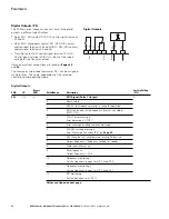
Digital Inputs, continued

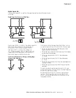
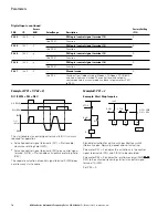
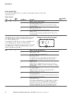
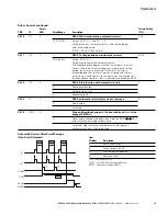
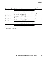
Example A: P3.1 = 1 (P6.8 = 0)

DI1 (FWD) + DI2 = REV

The start enable via control signal terminal 8 (DI1) is always 
required for operation:

Actuation control signal terminal 8 (DI1) = Start enable, 
clockwise rotating field (FWD)

Actuation control signal terminal 8 (DI1) plus control signal 
terminal 9 (DI2) = Start enable anticlockwise rotating field 
(REV)

The separate actuation of control signal terminal 9 (DI2) does 
not allow any start enable.

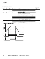
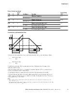
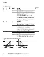
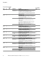
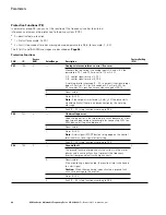
Example B: P3.1 = 2

Example: Start Stop Impulse

Standard actuation for a drive with pushbutton switch 
(Normally open, Normally closed) and self-actuating.

Parameter P3.1 = 2 enables this actuation via the control 
signal terminals 8 (DI1) and 9 (DI2) to be simulated.

Parameter P3.4 = 3 enables the rotation reversal (FWD 


REV) to be activated (reversing starter) via control signal 
terminal 10 (DI3).

Set P3.9 = 0.

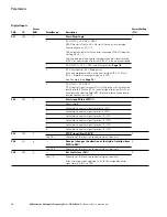
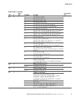
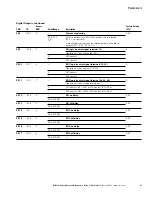
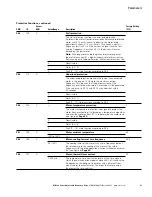
PNU

ID

Access
RUN

Value/Range

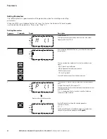
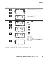
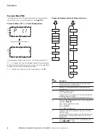
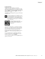
Description

Factory Setting
(P1.3)

P3.33

1420

DI3 logic (control signal terminal 10)

0

Like P3.31

Function

P3.34

1421

DI4 logic (control signal terminal 14)

0

Like P3.31

Function

P3.35

1422

DI5 logic (control signal terminal 15)

0

Like P3.31

Function

P3.36

1423

DI6 logic (control signal terminal 16)

0

Like P3.31

Function

P3.37

1480

Manual mode

0

Like P3.2

Changes from fieldbus mode (Modbus, CANopen, PROFIBUS, 
and so on) to manual mode. The control level and setpoint 
source required in manual mode can be set at parameters P6.31 
to P6.33.

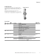
DI1 (FWD)

FWD

DI2 (REV)

REV

f

out

(Motor)

K1

K1

RUN

STOP

DI1

RUN

STOP

+24V

8

DI2

9

P3.4 = 3

DI3

10

OFF = FWD
ON  = REV

Summary of Contents for M-Max series

Page 1: ...M Max Series Adjustable Frequency Drive User Manual Effective October 2013 Supersedes February 2013 ...

Page 2: ......

Page 3: ...S FOR A PARTICULAR PURPOSE OR MERCHANTABILITY OTHER THAN THOSE SPECIFICALLY SET OUT IN ANY EXISTING CONTRACT BETWEEN THE PARTIES ANY SUCH CONTRACT STATES THE ENTIRE OBLIGATION OF EATON THE CONTENTS OF THIS DOCUMENT SHALL NOT BECOME PART OF OR MODIFY ANY CONTRACT BETWEEN THE PARTIES In no event will Eaton be responsible to the purchaser or user in contract in tort including negligence strict liabil...

Page 4: ...order stock availability or proof of shipment expediting an existing order emergency shipments product price information returns other than warranty returns and information on local distributors or sales offices Voice 877 ETN CARE 877 386 2273 8 00 a m 6 00 p m Eastern Time U S UTC 5 FAX 800 752 8602 After Hours Emergency 800 543 7038 6 00 p m 8 00 a m Eastern Time U S UTC 5 If you are in the U S ...

Page 5: ...very 5 Nameplate Rating Data 6 Catalog Number Selection 7 Technical Data and Specifications 9 Description of the M Max 13 Features 13 Selection Criteria 15 Proper Use 16 Maintenance and Inspection 16 Storage 17 Charging DC Link Capacitors 17 Service and Warranty 17 ENGINEERING Introduction 18 Electrical Power Network 19 Safety and Switching 21 EMC Measures 22 Motor and Application 23 INSTALLATION ...

Page 6: ... SERIAL INTERFACE MODBUS RTU General Information About Modbus 131 Communications in a Modbus Network 131 Modbus Parameters 132 Modbus Process Data 137 APPENDIX A Special Technical Data 142 Dimensions and Frame Sizes 148 PC Interface Card 151 Mounting Frame for Fieldbus Connection 153 PROFIBUS DP Fieldbus Interface Card 157 Cables Fuses and Disconnect Devices 158 List of Parameters 161 APPENDIX B D...

Page 7: ... Due to Increased Circulation with Device Fan 27 Mounting Dimensions 28 Configuration for Mounting with Screws 28 Mounting Rail Conforming with IEC EN 60715 29 Fastening to the Mounting Rail 29 Demounting 29 Mounting the Cable Routing Plate and the Brackets 29 EMC Compliant Setup Example M Max 31 Three Phase Input Connection 33 Connection to Power Section 33 Ground Connection 33 Connection in Power...

Page 8: ...ft Rotating Field REV for example 12 34 Hz 53 Start Stop Command with Maximum Setpoint Value Voltage Acceleration Ramp 3s 54 Brief Instructions Steps to the Motor Start 55 Example of an Error Message Undervoltage 56 Example of an Alarm Message 56 View of the Keypad with LCD Display Function Keys and Interface LCD Liquid Crystal Display 60 LCD Display Areas 61 Operational Data Indicator Operational...

Page 9: ...mes 124 Operational Data Indicator 127 Modbus Network with M Max 131 Data Exchange Between Master and Slave 133 Dimensions and Frame Sizes FS1 FS3 FS Frame Size 148 Dimensions and Frame Sizes FS4 and FS5 FS Frame Size 149 Equipment Supplied MMX COM PC 151 Fitting the MMX COM PC Connection Module 151 Removing the MMX COM PC Connection Module 151 Upload 152 Download 152 Inserting the 9V Block Batter...

Page 10: ...ifications on Control Signal Terminals 39 Factory Set Control Terminal Functions 40 List of Fault Messages F and Warning Messages AL 57 Error Messages via Operating Unit 59 Control Unit Elements 60 Areas of the LCD Display 61 Setting Parameters 62 Predefined Application Parameters from Parameter P1 2 66 Default I O 67 Parameter Selections 67 Analog Inputs 68 Digital Inputs 72 Analog Outputs 77 Dig...

Page 11: ...nect Devices 160 Quick Start Parameter Guide 161 System Parameters in the Quick Start 162 Default I O 163 Parameter Selection 164 Analog Input 164 Digital Input 165 Analog Output 166 Digital Output 167 Drives Control 168 Motor 170 Protective Functions 170 PID Controller 171 Fixed Frequencies 172 V Hz Characteristic Curve 173 Braking 174 Logic Function 175 Second Parameter Set 176 System Parameters...

Page 12: ...ures should be taken to ensure the proper restart of programs interrupted after a voltage dip or failure This should not cause dangerous operating states even for a short time If necessary emergency stop devices should be implemented Wherever faults in the automation system may cause injury or material damage external measures must be implemented to ensure a safe operating state in the event of a ...

Page 13: ...nly one hand when checking components Always work with another person in case an emergency occurs Disconnect power before checking controllers or performing maintenance Be sure equipment is properly grounded Wear safety glasses whenever working on electronic controllers or rotating machinery Warnings and Cautions CAUTION When selecting the cable cross section take the voltage drop under load condi...

Page 14: ...has been switched off intermediate circuit capacitor discharging time Pay attention to hazard warnings WARNING Discharge yourself on a grounded surface before touching the control signal terminals and the controller PCB This protects the device from destruction by electrostatic discharge WARNING On the control signal and the connection terminals of the frequency inverter no leakage resistance test...

Page 15: ...EAF Restart after FAULT and the error message has been acknowledged Reset WARNING If a start command is present at a digital input DI1 DI6 assigned at P3 21 the sequence control also starts automatically without switch edge when the power supply is switched on for example after a power supply failure CAUTION A high torque at low speed causes a high thermal load on the motor If temperatures are too...

Page 16: ...M Max Series Adjustable Frequency Drive xiv M Max Series Adjustable Frequency Drive MN04020003E October 2013 www eaton com ...

Page 17: ...h its housing placed properly as well as with all required safety relevant parts Please follow the installation instructions in the AWA8230 2416 installation instructions document This manual was created in an electronic format You can also order a hard copy version of it All the specifications in this manual refer to the hardware and software versions documented in it More information on the seri...

Page 18: ... ULN 14 in load networks while in the 400V category it takes into account the North American line voltage of 480V 10 60 Hz The permissible connection voltages for the M Max series are listed in Appendix A The rated operational data of the input voltage is always based on the input frequencies 50 60 Hz 50 Hz 10 to 60 Hz 10 Units Every physical dimension included in this manual uses imperial units F...

Page 19: ...cal systems and machines as well as with reading technical drawings Notes on the Second MMX Upgrade This second edition of the manual describes the extended functionality of the MMX This applies to M Max series frequency inverters from production date 12W10 S N 91275113 see nameplate Essential features of this upgrade New control circuit board with a more powerful microprocessor Side mounted inter...

Page 20: ...ber Description 1 Frequency inverters MMX _ 2 Mounting frame for fieldbus connection MMX NET XA 3 Fieldbus connection CANopen XMX NET CO A PROFIBUS DP with XMX NET PS A screw terminals PROFIBUS DP with XMX NET PD A Sub Dm connector DeviceNet XMX NET DN A 4 Communication module MMX COM PC IP21 kit I OK BACK RESET LOC REM COMM AC DRIVE ERROR 1 4 2 3 ...

Page 21: ...only be shipped in their original packaging with suitable transportation materials Please take note of the labels and instructions on the packaging as well as of those meant for the unpacked device Open the packaging with adequate tools and inspect the contents immediately after receipt in order to ensure that they are complete and undamaged The packaging must contain the following parts M Max fre...

Page 22: ...ecimal 3 F Integrated radio interference suppression filter 0 IP20 protection type 0 No integrated optional assembly Input Power connection rating Three phase AC voltage Ue 3 AC 380 480V voltage 50 60 Hz frequency input phase current 4 0A Output Load side motor rating Three phase AC voltage 0 Ue output phase current 3 3A output frequency 0 320 Hz Power Assigned motor rating 1 1 kW at 400V 1 5 hp a...

Page 23: ...es frequency inverter are in the following order Type Designation of the M Max Frequency Inverters Software Designation Series AA Description MMX Base catalog number MMX 1 1 AA 1D1 F 0 0 Phase 1 Single phase 3 Three phase Voltage 1 120V 2 230V 4 480V 5 575V Output Current 1D6 1 6A 010 10A EMC Filter F Filter N No filter Enclosure Class 0 NEMA 0 or IP20 1 IP21 or NEMA 1 Option 0 Full version ...

Page 24: ...lter 0 IP20 protection type 0 No integrated optional assembly MMX32AA2D4N0 0 MMX M Max series frequency inverter 3 Three phase input supply voltage 2 Rated voltage 230V AA Type of software version and display unit 2D4 2 4A rated operational current N No integrated interference suppression filter no filter 0 IP20 protection type 0 No integrated optional assembly MMX34AA012F0 0 MMX M Max series freq...

Page 25: ...F C 40 to 158 40 to 70 Installation altitude H ft m 0 3281 ft 0 1000m above sea level over 3281 ft 1000m with 1 power reduction per 328 ft 100m maximum 6562 ft 2000m at maximum 122 F 50 C ambient temperature Mounting position Vertical 90 for FS1 FS3 Vertical 30 for FS4 and FS5 Protection type IP20 for FS1 FS3 IP21 NEMA for FS4 and FS5 Busbar tag shroud BGV A3 VBG4 finger and back of hand safe Mech...

Page 26: ...tput voltage U2 V 3 AC 230 MMX11 3 AC Ue MMX12 MMX32 MMX34 MMX35 Output frequency f2 Hz 0 320 Frequency resolution setpoint value I Hz 0 01 Rated operational current I Ie 100 continuous current at maximum 122 F 50 C ambient temperature Overload current I Ie 150 for 60s every 600s Starting current I Ie 200 for 2s every 20s Braking torque MB MN 30 for all sizes Up to maximum 100 MN only as of size M...

Page 27: ...2 0 55 2 7 3 4 2 2 FS2 MMX11AA3D7_ 3 7 5 6 0 75 3 2 1 3 2 FS2 MMX11AA4D8_ 4 8 7 2 1 1 4 6 1 1 2 4 2 FS3 1 AC 230V 50 60 Hz 177 264V 0 45 66 Hz 0 MMX12AA1D7_ 1 7 2 6 0 25 1 4 1 4 1 5 FS1 MMX12AA2D4_ 2 4 3 6 0 37 2 1 2 2 2 FS1 MMX12AA2D8_ 2 8 4 2 0 55 2 7 3 4 2 2 FS1 MMX12AA3D7_ 3 7 5 6 0 75 3 2 1 3 2 FS2 MMX12AA4D8_ 4 8 7 2 1 1 4 6 1 1 2 4 2 FS2 MMX12AA7D0_ 7 10 5 1 5 6 3 2 6 8 FS2 MMX12AA9D6_ 9 6 ...

Page 28: ... kW A hp A 3 AC 400V 50 60 Hz 323 528V 0 45 66 Hz 0 MMX34AA1D3_ 1 3 2 0 37 1 1 1 2 1 1 FS1 MMX34AA1D9_ 1 9 2 9 0 55 1 5 3 4 1 6 FS1 MMX34AA2D4_ 2 4 3 6 0 75 1 9 1 2 1 FS1 MMX34AA3D3_ 3 3 5 1 1 2 6 1 1 2 3 FS2 MMX34AA4D3_ 4 3 6 5 1 5 3 6 2 3 4 FS2 MMX34AA5D6_ 5 6 8 4 2 2 5 3 4 8 FS2 MMX34AA7D6_ 7 6 11 4 3 6 6 4 6 4 FS3 MMX34AA9D0_ 9 13 5 4 8 5 5 7 6 FS3 MMX34AA012_ 12 18 5 5 11 3 7 1 2 11 FS3 MMX34...

Page 29: ...s for mounting on mounting rail DIN EN 50022 35 4 Interface for fieldbus connection modules option MMX NET XA 5 EMC installation accessories 6 Power section terminals 7 Cover flap of control signal terminals and microswitches 8 Interface for PC connection module MMX COM PC option 9 Keypad with 9 control buttons 10 Display unit LCD 7 8 9 10 1 2 3 4 6 5 I OK BACK RESET LOC REM Item Number Descriptio...

Page 30: ...R and R for external braking resistor only for MMX32 and MMX34 from frame size FS2 7 Inverter The IGBT based inverter converts the DC voltage of the DC link UDC into a three phase AC voltage U2 with variable amplitude and frequency f2 Sinusoidal pulse width modulation PWM with V f control can be switched to speed control with slip compensation 8 Motor connection U T1 V T2 W T3 with output voltage ...

Page 31: ...he total resulting current If necessary for dampening and compensating the deviating current values motor reactors or sinusoidal filters must be connected between the frequency inverter and the motor The parallel connection of multiple motors in the output of the frequency inverter is only permitted with V Hz characteristic curve control If you connect a motor to an operational frequency inverter ...

Page 32: ...inals U V W you must not connect a voltage or capacitive loads for example phase compensation capacitors connect multiple frequency inverters in parallel make a direct connection to the input bypass Observe the technical data and connection requirements For additional information refer to the equipment nameplate or label at the frequency inverter and the documentation Any other usage constitutes i...

Page 33: ...ust then be set to the values of the corresponding DC link voltage UDC and fed for around two hours regeneration time MMX12 MMX32 about 324 Vdc 1 41 x ULN with single phase line to line voltage 230V MMX34 about 540 Vdc 1 35 x ULN with three phase line to line voltage 400V MMX35 contact your local Eaton sales office for details MMX11 Due to the internal voltage doubler circuit the capacitors cannot ...

Page 34: ...input voltage input frequency interaction with p f correction systems 2 Breakers fuses and cable cross sections 3 Protection of persons and domestic animals with residual current protective devices 4 Input contactor 5 Input line reactor radio interference suppression filter input filters 6 Frequency inverter mounting installation power connection EMC measures circuit examples 7 Motor reactor dv dt...

Page 35: ...ent Measures for electromagnetic compatibility are mandatory in a drive system in order to meet the legal requirements for EMC and low voltage regulations Good grounding measures are a prerequisite for the effective insert of further measures such as shielding or filters Without respective grounding measures further steps are superfluous Input Voltage and Frequency The standardized input voltages ...

Page 36: ...h non choked idle current compensation devices current deviations can enable parallel resonance and undefinable circumstances In the project planning for the connection of frequency inverters to AC power networks with undefined circumstances consider using main chokes Input Reactors A input reactor also called commutation inductor increases the inductance of the power supply line This extends the ...

Page 37: ...tion A shielded cable is not required on the input side A completely 360 shielded low impedance cable is required on the motor side The length of the motor cable depends on the RFI class and must not exceed 98 ft 30m for the M Max Residual Current Device RCD RCD Residual Current Device Residual current device residual current circuit breaker FI circuit breaker Residual current circuit breakers pro...

Page 38: ...dard IEC EN 61800 3 This includes the complete power drive system PDS from the input supply to the motor including all components as well as cables see figure on Page 18 This type of drive system can consist of several individual drives The generic standards of the individual components in a PDS compliant with IEC EN 61800 3 do not apply These component manufacturers however must offer solutions t...

Page 39: ...tional current V Hz control parallel control of several motors The sum of the motor currents plus the motors inrush currents must be less than the frequency inverter s rated operational current Parallel operation at different motor speeds can be implemented only by changing the number of pole pairs and or changing the motor s transmission ratio CAUTION Debounced inputs may not be used in the safet...

Page 40: ... characteristic curve the motor also works in the range from 50 to 87 Hz with an unattenuated field The pull out torque remains at the same level as in input operation with 50 Hz The heat class of the motor must be at least F in 87 Hz operation V Hz Characteristic Curve The following table shows the allocation of possible frequency inverters depending on the input voltage and the type of circuit A...

Page 41: ...onnecting EX Motors Note the following when connecting explosion protected motors The frequency inverter must be installed outside the EX area Note the branch and country specific standards for explosion protected areas ATEX 100a Note the standards and information of the motor manufacturer regarding operation on frequency inverters for example if motor reactors du dt limiting or sinus filters are sp...

Page 42: ...ctions The instructions for installation in this manual apply for M Max series frequency inverters under protection type IP20 In order to meet the requirements in accordance with NEMA 1 IP21 you must depending on the size of the housing use the optional housing accessories MMX IP21 FS1 MMX IP21 FS2 or MMX IP21 FS3 The required installation instructions are shown in the setup instructions AWA8230 2...

Page 43: ...ency inverter switched mode power supply unit With MMX34 014_ the side clearance to a passive neighbor must always be 20 mm in all operating conditions and always 50 mm to the active neighbor Note Please note that the installation makes it possible to open and close the control signal terminal covers without any problems Note The pulse frequency fPWM can be adjusted with parameter P11 9 Note Devic...

Page 44: ...e holes mounting dimensions a1 and b1 shown in the figure below are also imprinted in the base plate of the M Max device FS1 FS3 Mounting Dimensions Install the screws in the specified positions first Then set the frequency inverter on the prepared wall mount and tighten all screws Configuration for Mounting with Screws 0 28 in 7 mm b1 a1 a1 mm in b1 mm in Mass kg lb Torque Nm ft lb Mounting Screw ...

Page 45: ...r blade width 0 20 in 5 mm is recommended for pushing the clip down Demounting Cable Flange Plate Accessories The M Max is supplied with a cable routing plate and brackets These enable you to arrange the connection cables as required on the frequency inverter and fasten the shielded cables in accordance with EMC requirements First install the cable clamp plate for the connection lines in the power...

Page 46: ...es Avoid using painted surfaces anodized chromized An overview of all EMC measures is provided in the figure on Page 31 Install the frequency inverter as directly as possible without spacers on a metal plate mounting plate Route input and motor cables in the switch cabinet as close to the ground potential as possible This is because free moving cables act as antennas When laying HF cables for exam...

Page 47: ...ng surfaces of frequency inverter and cable shielding must be free from paint Connect the cable shielding in the output of the frequency inverter with a large surface area contact to the ground potential PES Large area cable shield contacts with motor Large area earth connection of all metallic parts PE PES W2 U2 V2 U1V1 W1 PE 11 81 in 115 120 Vac 230 240 Vac 400 Vac 460 480 Vac 575 Vac 24 Vdc 115...

Page 48: ...ble nominal current value CAUTION Debounced inputs may not be used in the safety circuit diagram Ground contact currents in frequency inverters are greater than 3 5 mA AC According to product standard IEC EN 61800 5 1 an additional equipment grounding conductor must be connected or the cross section of the equipment grounding conductor must be at least 0 39 in2 10 mm2 WARNING The components in the...

Page 49: ...ble routing plate for shielded cables R R Connection terminals for external brake resistance only with MMX32_ MMX34_ and MMX35_ output braking transistor Connection to Power Section Ground Connection The ground connection is connected directly with the cable clamp plates The shielded cables between the frequency inverter and the motor should be as short as possible Connect the shielding on both en...

Page 50: ...8 0 0 80 20 0 0 30 8 0 1 40 35 0 0 30 8 0 0 80 20 0 0 30 8 0 1 40 35 0 0 30 8 0 0 80 20 0 0 30 8 0 1 40 35 0 FS2 0 30 8 0 0 80 20 0 0 30 8 0 1 40 35 0 0 30 8 0 0 80 20 0 0 30 8 0 1 40 35 0 0 30 8 0 0 80 20 0 0 30 8 0 1 40 35 0 FS3 0 30 8 0 0 80 20 0 0 30 8 0 1 40 35 0 0 30 8 0 0 80 20 0 0 30 8 0 1 40 35 0 0 30 8 0 0 80 20 0 0 30 8 0 1 40 35 0 FS4 0 30 8 0 1 60 40 0 0 30 8 0 1 20 30 0 0 30 8 0 2 00...

Page 51: ... the equalizing current loads on the shielding braid Connection with Twisted Cable Shielding Recommended value for twisted cable shielding b 1 5 a Twisted shielding braid should be connected with a ring cable terminal see figure on Page 33 on PES The following figure shows the construction of a four wire shielded motor line recommended specifications Four Core Shielded Motor Supply Cable If there ...

Page 52: ... 5 24 12 8 0 31 0 5 0 6 0 37 0 44 0 6 x 3 5 MMX32AA1D7_ MMX32AA2D4_ MMX32AA2D8_ 0 2 2 5 24 12 8 0 31 0 5 0 6 0 37 0 44 0 6 x 3 5 MMX34AA1D3_ MMX34AA1D9_ MMX34AA2D4_ 0 2 2 5 24 12 8 0 31 0 5 0 6 0 37 0 44 0 6 x 3 5 FS2 MMX11AA1D7_ MMX11AA2D4_ MMX11AA2D8_ MMX11AA3D7_ 0 2 2 5 24 12 8 0 31 0 5 0 6 0 37 0 44 0 6 x 3 5 MMX12AA3D7_ MMX12AA4D8_ MMX12AA7D0_ 0 2 2 5 24 12 8 0 31 0 5 0 6 0 37 0 44 0 6 x 3 5 ...

Page 53: ...X34AA9D0_ MMX34AA012_ MMX34AA014_ 0 2 4 24 10 8 0 31 0 5 0 6 0 37 0 44 0 6 x 3 5 FS4 MMX32AA017_ MMX32AA025_ 0 5 16 20 6 8 0 39 1 2 1 5 0 88 1 11 0 6 x 3 5 MMX34AA016_ MMX34AA023_ 0 5 16 20 6 8 0 39 1 2 1 5 0 88 1 11 0 6 x 3 5 FS5 MMX32AA031_ MMX32AA038_ 0 5 16 20 6 8 0 39 1 2 1 5 0 88 1 11 0 6 x 3 5 MMX34AA031_ MMX34AA038_ 0 5 16 20 6 8 0 39 1 2 1 5 0 88 1 11 0 6 x 3 5 M3 L3 L2 N U T1 V T2 W T3 L...

Page 54: ... of the shielding or with a rubber grommet on the end of the shielding Prevent the Shield from Becoming Unbraided As an alternative in addition to a broad area cable clip you can also twist the shielding braid at the end and connect to protective ground with a cable clip To prevent EMC disturbance this twisted shielding connection should be made as short as possible see figure on Page 35 Example f...

Page 55: ...the cover plate These are used to directly configure the control signal terminals Microswitch Factory Settings 1 2 3 6 7 8 9 10 25 24 4 5 13 14 15 16 18 20 22 23 26 AI2 DO GND DI4 DI5 DI6 AO DO R13 R14 R24 10V AI1 GND 24V DI C DI1 DI2 DI3 A B R21 R22 M3 mm2 mm2 AWG mm Nm ft lbs mm 0 14 1 5 0 25 0 5 26 16 5 0 22 0 25 0 16 0 18 0 4 x 2 5 1 2 3 6 7 8 9 10 25 24 4 5 13 14 15 16 18 20 22 23 26 AI2 DO G...

Page 56: ...D start enable forward 0 30V Ri 12k ohms 9 DI2 Digital input 2 REV start enable reverse 0 30V Ri 12k ohms 10 DI3 Digital input 3 Fixed frequency B0 0 30V Ri 12k ohms 13 DO Digital output Active READY Transistor max 50 mA supply voltage control signal terminal 20 14 DI4 Digital input 4 Fixed frequency B1 0 30V Ri 12k ohms 15 DI5 Digital input 5 Error acknowledgment 0 30V Ri 12k ohms 16 DI6 Digital ...

Page 57: ... on Page 68 The AI1 analog input control signal terminal 2 is factory set for the frequency setpoint P6 2 The setpoint can be input via an external potentiometer recommended fixed resistance 1 10k ohms The fixed resistance of the setpoint potentiometer is fed from the frequency inverter via control signal terminal 1 with 10V maximum load rating 10 mA Control signal terminals 3 and 5 are reference ...

Page 58: ... with a residual ripple less than 5 Ua Ua The parameterizable functions are described in Digital Inputs P3 on Page 71 Digital Inputs with Internal Supply Voltage Digital Inputs with External Supply Voltage The factory set functions and the electrical connection data are shown in Control Signal Terminal Functions on Page 40 Microswitch S1 LOGIC is used to change the control logic to so called negat...

Page 59: ...oltage of up to 48V The permissible residual ripple must be less than 5 Ua Ua The maximum permissible load current is 50 mA Digital Output DO and Connection Examples Coupling Relay with Freewheeling Diode ETS4 VS3 Item No 083094 Connection Example and Operation of DO in Source and Sink Type The parameter assignment is described in Digital Outputs P5 on Page 78 7 8 9 DI1 DI2 DI_COM 6 50 mA 24V Out ...

Page 60: ...d fasten the connection cables of the relay in the opening on the right housing Fixed Connection Cables at U 48V Relay The functions for which parameters can be defined are described in Digital Outputs P5 on Page 78 The factory setting causes N O contact R13 R14 control signal terminal 22 23 of relay RO1 to indicate operation RUN N O contact R21 R24 control signal terminal 25 26 of relay RO2 indic...

Page 61: ...d at the end of a data cable is integrated in the frequency inverter and can be connected via microswitch S4 The network cable must have a bus termination resistor 120 ohms connected at each physical end to prevent reflections and the resulting transmission faults Two Wire RS485 Connection Slave M Max Frequency Inverter The parameter definition of the serial interface is described in Serial Interf...

Page 62: ... circuit inside the internal DC link A power supply of 1 AC 120V 115V will output a motor voltage of 3 AC 230V Error Run Ready 23 22 PE PE W V U M 3 X1 A B 24 26 25 1 2 3 5 4 AO 0 4 20 mA 0 10V 10 mA 7 8 9 18 DI1 DI2 AI1 DI3 DI4 DI5 DI6 GND DI_COM 10 mA 10 V Out 14 15 16 10 R13 R14 R21 R22 R24 S4 S3 S2 S1 FWD REV FF1 FF2 24V 6 50 mA 24V Out GND 120 ohms 50 mA DO DO 13 20 0 10V L3 200k ohms 200k oh...

Page 63: ...W V U M 3 X1 A B 24 26 25 1 2 3 5 4 AO 0 4 20 mA 0 10V 10 mA 7 8 9 18 DI1 DI2 AI1 DI3 DI4 DI5 DI6 GND DI_COM 10 mA 10V Out 14 15 16 10 R13 R14 R21 R22 R24 S4 S3 S2 S1 FWD REV FF1 FF2 24V 6 50 mA 24V Out GND 120 ohms 50 mA DO DO 13 20 0 10 V L1 200k ohms 200k ohms 200 ohms 200 ohms AI2 f Out PI Ist EMC Reset PI Off f Soll 3 AC 230V 1 AC 230V 1 AC 240V ...

Page 64: ...S3 drives EMC filter only available on MMX34 units PE R R Error Run Ready 3 AC 3 AC 23 22 PE PE W V U M 3 X1 A B 24 26 25 1 2 3 5 4 AO 0 4 20 mA 0 10V 10 mA 7 8 9 18 DI1 DI2 AI1 DI3 DI4 DI5 DI6 GND DI_COM 10 mA 10V Out 14 15 16 10 R13 R14 R21 R22 R24 S4 S3 S2 S1 FWD REV FF1 FF2 24V 6 50 mA 24V Out GND 120 ohms 50 mA DO DO 13 20 0 10V L1 L3 200k ohms 200k ohms 200 ohms 200 ohms AI2 f Out PI Ist EMC ...

Page 65: ...the insulation resistance of the motor cable between the individual phase conductors and between the phase conductor and the protective conductor The insulation resistance must be greater than 1M ohm Testing the Input Cable Insulation Disconnect the power cable from the input supply network and from connection terminals L1 L2 N and L3 of the frequency inverter Measure the insulation resistance of ...

Page 66: ...rly PE 6 All electrical terminals in the power section L1 L2 N L3 U T1 V T2 W T3 R R PE were implemented properly and were designed in line with the corresponding requirements 7 Each single phase of the supply voltage L1 L2 L3 is protected with disconnect device 8 The frequency inverter and the motor are adapted to the input voltage see Nameplate Rating Data on Page 6 connection type star delta of...

Page 67: ...automatically when the supply voltage is switched back on if the automatic restart function has been enabled See parameter P6 13 CAUTION Debounced inputs may not be used in the safety circuit diagram Any contactors and switching devices on the power side are not to be opened during motor operation Inching operation using the power switch is not permitted Contactors and switching devices repair and...

Page 68: ... and all segments are displayed briefly The frequency inverter runs a self test automatically when the power is applied The arrows in the top status line of the LCD display show the operating status READY proper operating status STOP stop no start command The arrows in the bottom status line show the controller commands Actuation is done via the control signal terminals I O Control Input Output in...

Page 69: ...otentiometer via terminal 2 proportional voltage signal 0 10V The change in output frequency here is delayed based on the specified acceleration and deceleration ramps In the factory settings these times are set to 3 seconds The acceleration and deceleration ramps specify the time change for the output frequency from zero to fmax FS 60 Hz or from fmax back to zero The figure on Page 54 shows a goo...

Page 70: ... display M1 1 0 00 Hz The frequency inverter is now ready for operation and is factory set for activation and frequency setting via the control signal terminals I 0 The STOP button is active in this mode Changes are only possible when there is flashing at the entry digit press OK button The direction can be changed via the two arrow buttons or cursor The drive is factory set to stop at 0 Hz and ca...

Page 71: ...ON PAR FLT OR LOC REM RUN STOP ALARM FAULT READY REF FWD REV I O KEYPAD BUS MON PAR FLT OK RUN STOP ALARM FAULT READY REF FWD REV I O KEYPAD BUS MON PAR FLT Self Test Set RUN STOP ALARM FAULT READY REF FWD REV I O KEYPAD BUS MON PAR FLT OK 1 10V AI1 GND 24V DI1 DI2 2 3 6 8 9 4K7 M R11 M FWD REV Start Stop FWD REV RUN R11 Frequency Set Value STOP I OK Ready to Start Start Run Set Save Stop 0 Hz Cur...

Page 72: ...lt Log FLT The last nine faults can be called up and shown in succession in the fault log FLT Select the FLT menu level Use the arrow buttons and to call the faults F1 F9 individually Every error message is stored with the time of the error occurrence under d day H hour and m minute The call is made with the OK button and the selection with the and arrow buttons The content of the error memory is ...

Page 73: ...itch temperature is above 248 F 120 C An excessive temperature warning is issued if the IGBT switch temperature goes above 230 F 110 C Make sure that there is an unobstructed flow of cooling air Check the ambient temperature Make sure that the switching frequency is not too high in relation to the ambient temperature and to the motor load 15 Motor stalled The motor blocking protection mechanism ha...

Page 74: ...e device indicated by the error message Check the cabling for the respective device as well 53 Fieldbus error The communication link between the master device and the drive s fieldbus has been interrupted Check the installation Further notes are provided in the manual of the optional fieldbus interface CANopen PROFIBUS DP and so on If the installation is okay contact your local representative 54 F...

Page 75: ...ample Actuate the BACK RESET button or terminal DI5 reset to acknowledge the error message The acknowledged fault message is displayed with READY and the failure code By actuating the OK button the number of operating days for example d 13 days until this fault message is displayed You can also show the respective hours H and minutes M of operation with the arrow button You exit the fault log FLT ...

Page 76: ...essage Reset Activates the selection for the menu levels flashes Move between different control levels I O KEYPAD BUS according to parameter settings P6 1 and P6 17 Select function and parameter Increase numerical value Confirm and activate selection store Lock display Select function and parameter Reduce numerical value Move to the individual parameter groups S4 1 P1 1 P2 1 P3 1 In displays with ...

Page 77: ...inverter is ready for operation and can be started via the control signal terminal with the specified values from the factory settings when connecting the allocated motor output see Commissioning with Control Signal Terminals Factory Setting on Page 52 Area Description 1 Status indicator The arrowheads on the top border show information regarding the drive READY Ready to start RUN Operating notifi...

Page 78: ...al data indicator monitor PAR Parameter levels FLT Fault log Fault Use the OK button to open the selected main menu 2 The numerical first value is always shown from the selected main menu Example Main menu PAR Parameter P1 1 The display automatically switches between the parameter number and the defined value P1 1 1 is displayed at the first switch on and after the factory settings have been activ...

Page 79: ... respective parameter number 4 The other parameters in the main menu PAR can be selected with the two arrow buttons or closed circuit Example Factory setting The arrow buttons and enable you to select the first parameter of each parameter group P1 1 P2 1 P3 1 P4 1 S4 1 S3 1 S2 1 S1 1 P14 1 5 By actuating the BACK RESET button you exit main menu PAR arrow flashes see sequence 1 RUN STOP ALARM FAULT...

Page 80: ...d selected parameters with the Quickstart Wizard use OK button to move further B Free access to all parameters move further using the four arrow buttons 1 Parameter conceal selection P1 1 1 Factory setting The quick start assistant guides you to the selected parameters predefined parameter change P1 1 0 allows access to all parameters free parameter selection 2 Selection of pre defined parameter v...

Page 81: ... to call up the parameters of the quick configuration and then change them freely Besides the parameters of the quick configuration system parameters S1 1 to S4 3 are also shown after the first setting P1 1 0 activates access to all parameters and the full functionality of all buttons of the keypad free parameter definition see B in the figure on Page 64 This exits the quick configuration and the ...

Page 82: ...2 Fan drive 3 Hoisting device high load Application P1 3 1 N A 1 N A 1 N A 1 N A Country specific default settings P6 1 1 Control signal terminals I O I O 1 Control signal terminals I O I O 1 Control signal terminals I O I O 1 Control signal terminals I O I O Primary remote control source P6 2 3 AI1 analog setpoint 1 3 AI1 analog setpoint 1 3 AI1 analog setpoint 1 3 AI1 analog setpoint 1 Primary r...

Page 83: ...v P3 1 P3 3 RO1 NO 22 23 Run P5 1 P5 10 DI3 10 Fixed Frequency B0 12 Hz P3 9 P10 2 RO2 NO NC 24 25 26 Fault P5 2 P5 11 DI4 14 Fixed Frequency B1 18 Hz P3 10 P10 3 DO 13 Ready P5 3 P5 9 DI5 15 Fault Reset P3 7 PNU ID Access RUN Value Range Description Factory Setting P1 3 P1 1 115 Quick start parameters 1 0 All parameters All parameters are shown and can be changed Exit from Quickstart 1 Only quick...

Page 84: ...st f Soll S2 AI1V 0 10V AI1 V mA S3 AI2 mA 4 20 mA AI1 V mA PNU ID Access RUN Value Range Description Factory Setting P1 3 P2 1 379 AI1 signal range analog input 0 Depending on the switch position of microswitch S2 FS frequency setpoint 0 S2 V 0 10V voltage signal FS see P6 2 S2 mA 0 20 mA current signal 1 With live zero S2 V 2 10V voltage signal S2 mA 4 20 mA current signal At P8 1 it is possible...

Page 85: ... 0 30 In relation to the 30 signal a constant offset signal of 23 is predefined in this case The scaled input signal AIscal is therefore 23 100 as frequency setpoint value 23 fmax fmax P6 4 as a process variable 23 100 actual value for the PID controller Example of Scaled Analog Input Signals with Offset PNU ID Access RUN Value Range Description Factory Setting P1 3 P2 5 390 AI2 signal range analo...

Page 86: ...s to 63 of the maximum analog signal 10V 20 mA Long filter times lead to a delay in the analog signal processing You can deactivate the filter time constant by setting the parameter to 0 0 P2 4 AI1 Filter time constant analog input AI1 P2 8 AI2 Filter time constant analog input AI2 P4 4 AO Filter time constant Analog output AO Filter Time Constant Notes Analog signal with faults unfiltered Filtered...

Page 87: ...inals I O with LOGIC Source type DI1 control signal terminal 8 FWD Forward Start enable clockwise rotating field DI2 control signal terminal 9 REV Reverse Start enable anti clockwise rotating field DI3 control signal terminal 10 FF1 fixed frequency 1 10 Hz DI4 control signal terminal 14 FF2 fixed frequency 2 15 Hz DI5 control signal terminal 15 Reset acknowledge error message ALARM DI6 control signal ...

Page 88: ...l terminal 8 starts the drive with a clockwise rotating field FWD and P3 3 control signal terminal 9 with an anticlockwise rotating field REV Both control commands are interlocked exclusive OR P3 2 403 Start signal Start FWD 1 1 0 Deactivated 1 Activated via control signal terminal 8 DI1 2 Activated via control signal terminal 9 DI2 3 Activated via control signal terminal 10 DI3 4 Activated via co...

Page 89: ... terminal DI1 to DI6 P3 7 414 Fault reset 5 Like P3 2 Allocation of the function to control signal terminals Acknowledges a displayed error message Reset when switching on 24V on the assigned control signal terminal DI1 to DI6 P3 8 407 Run enable 0 Like P3 2 Allocation of the function to control signal terminals Rotational direction independent start release when switching on 24V on the assigned c...

Page 90: ... deceleration time from dec1 P6 6 to dec2 P6 20 P3 16 1403 Stop acceleration deceleration time 0 Like P3 2 Assignment of control signal terminal Stops all acceleration P6 5 P6 19 P14 9 and deceleration times P6 6 P6 20 P14 10 P3 17 1404 Block parameter access 0 Like P3 2 Assignment of control signal terminal Blocks access to all parameters Note The resetting of all parameters to the default settin...

Page 91: ...levels set at P6 1 and P6 17 LOC REM function P3 26 1413 Activate secondary remote speed reference 0 Like P3 2 Assignment of control signal terminal Switch between the setpoint sources AI1 and AI2 set at P6 2 and P6 18 P3 27 1414 Activate second parameter set 2PS 0 Like P3 2 Assignment of control signal terminal The values set at the parameter group P14 are activated P3 28 1415 Fieldbus remote inp...

Page 92: ...P3 1 2 enables this actuation via the control signal terminals 8 DI1 and 9 DI2 to be simulated Parameter P3 4 3 enables the rotation reversal FWD REV to be activated reversing starter via control signal terminal 10 DI3 Set P3 9 0 PNU ID Access RUN Value Range Description Factory Setting P1 3 P3 33 1420 DI3 logic control signal terminal 10 0 Like P3 31 Function P3 34 1421 DI4 logic control signal t...

Page 93: ... frequency inverter Analog Output AO Analog Outputs 5 0 10V AO 18 GND 10 mA f Out PNU ID Access RUN Value Range Description Factory Setting P1 3 P4 1 307 AO signal Analog Output 1 0 Deactivated 1 Output frequency f Out 0 fmax P6 4 2 Output current I2 0 IN Motor P7 1 3 Torque MN 0 100 calculated value 4 PID controller output 0 100 P4 2 310 AO minimum value 1 0 0V 1 2V live zero P4 3 1456 AO gain 10...

Page 94: ...lected control level and operating mode Digital Outputs Digital Outputs 50 mA DO DO 13 20 23 22 24 26 25 R13 R14 R21 R22 R24 Error Run Ready PNU ID Access RUN Value Range Description Factory Setting P1 3 P5 1 313 RO1 Signal Relay 1 Output 2 0 Deactivated 1 READY the frequency inverter is ready for operation 2 RUN the inverter of the frequency inverter is enabled FWD REV 3 FAULT error message Error...

Page 95: ...2V P2 1 1 P2 5 1 24 LOG function fulfilled Message if the logical operation of P13 3 is fulfilled LOG 1 25 PID controller actual value monitoring Message if the actual value is within the hysteresis set at P9 15 and P9 16 26 External brake actuated Switch threshold set value of P12 8 27 Current monitoring Switch threshold set value of P5 8 28 Fieldbus remote output The assigned digital output is w...

Page 96: ... Frequency monitoring 2 0 Monitoring of the selected frequency range see P5 5 for explanation A monitoring message can be implemented via the digital outputs value 11 P5 1 P5 2 P5 3 0 Deactivated 1 0 00 P5 7 Hz frequency is below reference P5 7 2 P5 7 P6 4 Hz frequency is above reference P5 7 P6 4 maximum frequency P5 7 347 Frequency monitoring 2 reference value 0 00 0 00 P6 4 Hz P6 4 maximum freq...

Page 97: ...minal 13 0 Operation of transistor output DO 0 N O contact 1 N C contact P5 10 1331 RO1 logic control signal terminals 22 23 0 Operation of relay contact R13 R14 0 N O contact 1 N C contact P5 11 1332 RO2 logic control signal terminal 24 25 26 0 Operation of relay changeover contact 0 N O contact R21 R24 or N C contact R21 R22 1 N C contact R21 R24 or N O contact R21 R22 P5 12 1459 DO on delay 0 0...

Page 98: ...ion here 3 Fieldbus BUS You can switch directly between BUS and KEYPAD with the LOC REM button RUN STOP ALARM FAULT READY REF FWD REV I O KEYPAD BUS MON PAR FLT P6 2 117 Primary remote speed reference 3 0 Fixed frequency FF0 The value can be set in parameter P10 1 1 Operating unit REF This setting causes the setpoint defined at REF to be read It can be set via the keypad with the arrow buttons or ...

Page 99: ...ve than are set in P6 5 Large centrifugal masses or if driven by the load the deceleration time of the drive can be greater than is set in P6 6 Notes When setting a minimum output frequency P6 3 greater than 0 Hz the acceleration and deceleration time of the drive is reduced to t1 or t2 Reference points for the acceleration and deceleration times set in parameters P6 5 and P6 6 are always 0 Hz P6 ...

Page 100: ...eady turning at the start command with flow machines pumps fans and with short interruptions in input voltage P6 8 506 X Stop function 0 0 Free coasting The motor carries out an uncontrolled stop coasting after the start enable FWD REV is switched off or when the STOP button P6 16 is actuated 1 Ramp deceleration dynamic braking Deceleration time with the value set under P6 6 If the energy that is ...

Page 101: ...error is acknowledged after the test time has elapsed and the test time is only started again with the next error The number of fault occurrences before a fault is indicated is defined by P6 30 P6 12 719 X REAF Start function with automatic restart 0 0 Ramp acceleration 1 Flying restart circuit 2 According to P6 7 P6 13 731 X REAF automatic restart after an error message 0 0 Deactivated 1 Activate...

Page 102: ... Yes activated P6 17 1427 X Secondary remote control source 3 Assignment of the control levels as at P6 1 Control level 2 is activated via parameter P3 25 P6 18 1428 X Secondary remote speed reference 2 Assignment of setpoint sources as at P6 2 Setpoint source 2 is activated via parameter P3 26 P6 19 502 Secondary acceleration time acc2 10 0 0 1 3000s See Note 1 of parameter P6 5 The activation is...

Page 103: ... P6 27 512 X Skip frequency 2 upper value 0 00 P6 26 P6 4 Hz P6 28 513 X Skip frequency 3 lower value 0 00 0 00 P6 29 Hz P6 29 514 X Skip frequency 3 upper value 0 00 P6 28 P6 4 Hz Setting Range for Skip Frequencies P6 30 759 X Automatic REAF attempts 3 1 10 Define the permissible number of automatic restarts REAF Restart After Failure P6 31 1481 X Manual mode primary control source 1 Like P6 1 As...

Page 104: ... Type for Motor Stator Windings When selecting the rating data take the dependency of the type of switching on the strength of the feeding input voltage into account 230V P7 5 delta circuit A P7 1 4A 400V P7 5 star connection P7 1 2 3A Circuits Delta Star Example Single phase connection of the MMX12AA4D8_ frequency inverter to a input voltage of 230V The stator winding of the motor is connected in...

Page 105: ...er s rated operational current See figure on Page 88 P7 2 107 X Current limit 1 5 x Ie 0 2 x Ie 2 x Ie A Factory setting 1 5 x Ie P7 3 112 X Motor rated speed 1720 300 20000 RPM min 1 See figure on Page 88 P7 4 120 X Motor power factor cos 0 85 0 30 1 00 See figure on Page 88 P7 5 110 X Motor rated operating voltage 180 676V See figure on Page 88 Pay attention to the supply voltage and the type of...

Page 106: ...or 0 25V for 0 5 seconds This reaction time can be changed at P8 10 0 Deactivated 1 Alarm AL 50 Note If the setpoint is restored 4 mA 2V the drive starts up automatically if there is no disconnection by the warning message 2 Fault F 50 stop function according to P6 8 P8 2 727 X Undervoltage error 2 Under voltage error in the intermediate circuit because of a low input side supply voltage for examp...

Page 107: ...ncy This requires that the output current of the frequency inverter be monitored A message will be generated if the values set in P8 12 and P8 13 are undershot within 20 seconds 0 Deactivated 1 Alarm AL 17 2 Fault F 17 stop function according to P6 8 P8 6 704 X Motor temperature protection 2 The motor temperature protection is designed to protect the motor from overheating It is based on a tempera...

Page 108: ...he motor see thermistor protection offers great protection The reaction of the M Max frequency inverter to a detected thermal overload can be set via parameter P8 6 At parameter P8 8 you can set the cooling output PCool on the motor at zero frequency standstill Note the specifications of the motor manufacturer Possible setting values are 0 150 of the cooling output at the rated frequency fN see na...

Page 109: ... a detected underload can be set at P8 5 The value set here determines the lowest permissible torque limit This function can also be used with output frequencies that are above the cutoff frequency P11 2 field weakening point Note The value set here is reset automatically to the factory setting 50 0 if the parameter for the motor rated current P7 1 is changed Underload Limit P8 13 715 Underload lo...

Page 110: ...error if the fieldbus is set as active control level BUS P6 1 2 P6 17 2 0 Deactivated 1 Alarm AL 53 2 Fault F 53 stop function according to P6 8 P8 15 734 Fieldbus interface error 2 Reaction to a fieldbus interface error slot at the frequency inverter or when the fieldbus interface card is missing when the fieldbus is set as active control level BUS P6 1 2 P6 17 2 0 Deactivated 1 Alarm AL 54 2 Fau...

Page 111: ...o percentages For example the specified setpoint 0 100 here is the same as a volume flow 0 50 m3 h The actual value here is the volume flow m3 h from a suitable sensor which is evaluated again as a percentage 0 100 If this process data is to be displayed in the physical variable m3 h you can set the conversion with parameter P9 19 see Display factor P9 19 PID Controller PNU ID Access RUN Value Ran...

Page 112: ...ies an inverted signal Example With increasing pressure a pressure sensor output signal 10V 0V 0 max bar drops P9 10 132 PID controller D rate time 0 00 0 10s Differential time constant P9 11 1431 PID controller output filter delay time 0 0 0 00 10 00s P9 12 1016 Sleep mode frequency 0 00 0 P6 4 Hz The frequency inverter stops automatically if the frequency of the drive drops below the sleep level...

Page 113: ...steresis lower limit 0 0 0 00 100 See P9 15 P9 17 1435 PID controller max controller deviation 3 0 0 00 100 If the PID controller is activated P9 1 1 and the deviation between the setpoint and the actual value exceeds the value entered here the PID monitoring is activated Setting at P5 1 2 3 12 P9 18 1475 PID controller reference value scaling 1 0 1 32 7 Setpoint display multiplication of a factor...

Page 114: ...OD The PID system deviation e is the difference between reference and actual value process variable PV The digital output configured as OD is activated if a freely selectable control deviation P9 17 is exceeded with the PID controller P9 1 1 active The OD output stays activated until this limit value is exceeded If you wish to configure a parameterizable digital output or signalling relay as OD yo...

Page 115: ... diagram Start of fan motor M1 with FWD signal The actual value PV is below the limit value of P9 16 The FBV output P5 1 P5 3 25 then switches and fan motor M2 Start starts automatically The actual value rises and reaches the upper limit P9 15 The FBV output is automatically switched off fan M2 Off Fan M1 remains in operation and works in linear control mode In a correctly set up system this is th...

Page 116: ...F2 15 Hz and FF3 20 Hz can be called via digital inputs DI3 control signal terminal 10 and DI4 control signal terminal 14 in the factory setting Fixed Frequency The change between the individual fixed frequency values is completed with the acceleration and deceleration times set at P6 5 and P6 6 When the FWD or REV enables are switched off the output frequency is immediately blocked uncontrolled c...

Page 117: ...ust be assigned a third digital input For example P3 11 5 DI5 control signal terminal 15 This value can then be called up directly via DI3 Note In the factory setting DI5 control signal terminal 15 is assigned with the error acknowledgement Reset Setting P3 11 0 is recommended P10 6 128 Fixed frequency FF5 36 00 0 00 P6 4 0 00 Hz up to the maximum frequency value P6 4 For activation parameter P3 1...

Page 118: ...10 18 of the associated parameters are set 0s PNU ID Access RUN Value Range Description Factory Setting P1 3 P10 9 1436 PLC Sequence control operating mode 0 Selection of operating modes for cyclical program execution The start of the program execution via a digital input DI1 DI6 is executed according to parameter P3 21 The pause of the program execution via a digital input DI1 DI6 is executed acc...

Page 119: ...ge Description Factory Setting P1 3 P10 11 1438 Set time for FF0 0 0 1000s 0s Fixed frequency FF0 deactivated sequence control P10 9 P10 12 1439 Set time for FF1 0 0 1000s 0s Fixed frequency FF1 deactivated sequence control P10 9 P10 13 1440 Set time for FF2 0 0 1000s 0s Fixed frequency FF2 deactivated sequence control P10 9 P10 14 1441 Set time for FF3 0 0 1000s 0s Fixed frequency FF3 deactivated...

Page 120: ...ewed start command begins once more with the first fixed frequency A digital input DI1 DI6 can be assigned the Pause sequence control function at parameter 3 22 The program sequence is then stopped and can then be resumed from this stopping point fixed frequency The operating states of the sequence control can be displayed via the digital outputs RO1 RO2 and DO The following assignments are shown ...

Page 121: ...nce P10 10 192 see Page 102 This decimal program code 192 64 128 assigns the clockwise rotating field REV to fixed frequencies FF6 P10 7 and FF8 P10 8 Example B Program Cycle Executed Once P10 9 1 P10 10 192 P10 6 P10 8 P10 7 P10 5 P10 4 P3 21 P10 17 P10 18 P10 15 P10 16 P10 13 P10 14 P10 11 P10 12 f Hz FWD P5 3 18 P5 2 17 P5 1 16 P10 3 P10 2 P10 1 t REV 1 ...

Page 122: ...P10 18 have elapsed the output frequency is set to zero according to the Stop function P6 8 before the next numerically fixed frequency value is executed A clockwise rotating field REV can also be assigned here to the individual fixed frequencies as a decimal program number at parameter P10 10 see Page 102 Example C Program Cycle Executed Once in Steps P10 9 2 P10 10 0 P10 6 P10 5 P10 4 P10 7 P10 ...

Page 123: ...signed automatically and corresponds with the values of parameter P7 5 nominal motor voltage and P7 6 rated motor frequency If you require other values for the V Hz characteristic curve you must first set parameters P7 5 and P7 6 before you change the parameters of the V Hz characteristic curve shown here V Hz Characteristic Curve PNU ID Access RUN Value Range Description Factory Setting P1 3 P11 ...

Page 124: ...ere As of this cut off frequency the voltage frequency ratio is no longer constant The magnetization of the connected motor is reduced with increasing frequency field weakening range Example Linear V Hz Characteristic Curve with Cut Off Frequency and Field Weakening Range P11 3 603 X Output voltage 100 00 10 200 Input voltage In the standard application the value set here is equal to 100 of the in...

Page 125: ...If temperatures are too high the motor should be equipped with an external fan P11 7 109 X Torque increase 0 0 Deactivated 1 Enabled Automatic increase of the output voltage Boost with an increased load and low speed for example heavy starting duty Caution A high torque at low speed leads to a high thermal load on the motor Note If temperatures are too high the motor should be fitted with an exter...

Page 126: ...related deviations From the measured voltage and current values of the stator winding u1 i1 the internal motor model calculates the required manipulated variables for the flux variable iμ and the torque variable iw In the equivalent circuit diagram of the three phase motor the load related slip is shown as the resistance R 2 s In idle operation without a load this resistance approaches infinity an...

Page 127: ...creases with higher switching frequencies With motor frequencies 5 Hz a higher speed stability can be achieved at low switching frequencies Note As a protection against thermal overload MMX reduces the switching frequency automatically if for example too high values are set and with high ambient temperatures and high load currents Parameter P11 10 1 must be set for operation at a constant carrier ...

Page 128: ...r is at a standstill and disappears completely as soon as the rotor movement has ended DC braking is therefore not suitable for holding loads nor for intermediate braking Once DC braking has been activated the motor comes to a standstill CAUTION Debounced inputs may not be used in the safety circuit diagram DC braking results in additional heating of the motor Configure the brake torque set via bra...

Page 129: ...es the DC braking after a stop command FWD REV switched off Requirement P6 8 1 Stop function ramp The output frequency 1 is reduced after the stop command according to the deceleration time set at P6 6 Depending on inertia and the load torque the speed of the motor 2 is reduced accordingly and braked with DC current at the frequency value set here You can set the duration of the DC braking 3 under...

Page 130: ...ncy set under P12 3 with the braking time set here With P6 8 0 free run out the activation of the DC braking 3 occurs directly with the stop command If the output frequency 1 is greater than or equal to the rated motor frequency P7 6 the value set here is considered for the duration of the braking time If the output frequency is less than or equal to 1 of the rated motor frequency P7 6 the duratio...

Page 131: ...king torque of around 30 of the motor rated torque A higher braking torque can be achieved by selecting a more powerful frequency inverter From the 1 1 kW 3 3A at 400V MMX34AA3D3_ rating the internal brake chopper with an external power resistor enables up to 100 of the rated motor torque Regenerative Braking with External Braking Resistor The brake chopper can be activated at parameter P12 5 This...

Page 132: ... 14A The switching threshold for the brake transistor should always be above the maximum DC link voltage For example allowing for the maximum permissible input voltage peak of 10 ULN 400 Vac ULN 10 400 Vac 440 Vac UDC 1 35 x ULNmax 1 35 x 440V 594 Vdc maximum permissible DC link voltage in motor operation Allowing for an energy absorption from the DC link of around 30 during braking the on thresho...

Page 133: ...Brake released 2 Brake activates and brakes the drive mechanically P12 9 P12 8 f Hz R01 R02 DO P5 26 RUN FWD REV t STOP P6 8 1 1 2 PNU ID Access RUN Value Range Description Factory Setting P1 3 P12 7 1448 X External brake delay time opening 0 2 0 00 320 00s Condition RUN Start enable After the time set here has elapsed the brake is actuated P5 _ is opened P12 8 1449 X External brake frequency thre...

Page 134: ... P5 2 The type of operation And Or Exclusive Or is defined in parameter P13 3 Logic Linking of A and B Example Digital output RO1 N O contact R13 R14 is required to indicate during operation that the set current limit has been reached P5 1 24 LOG function fulfilled P13 1 2 Operation RUN signal A P13 2 27 Current monitoring signal B P13 3 0 A AND B 0 1 28 0 1 2 AAND B A OR B A XOR B P13 3 LOG A B P5...

Page 135: ...ency 0 Hz 10 Frequency monitoring 1 For the frequency ranges set at P5 4 and P5 5 11 Frequency monitoring 2 For the frequency ranges set at P5 6 and P5 7 12 PID monitoring For the deviation set at P9 17 13 Overtemperature signal 14 Overcurrent control active 15 Overvoltage control active 16 PLC Sequence control active 17 PLC Sequence control single step completed 18 PLC Sequence control program cy...

Page 136: ...lue of P5 8 28 Fieldbus Remote output The number of the assigned digital output is written directly to the control word ID2001 bit 13 P13 2 1454 X LOG function Selection input B 0 Like P13 1 P13 3 1455 X LOG function select operation 0 Logical operation LOG of the selected functions of parameter P13 1 A and P13 2 B 0 A AND B 1 A OR B 2 A XOR B exclusive A or B Signal Logic Link LOG XOR Exclusive o...

Page 137: ...Default values vary based on actual unit ratings PNU ID Access RUN Value Range Description Factory Setting P1 3 P14 1 1347 X Motor rated current 2PS Ie 0 2 x Ie 2 x Ie Ie Rated operational current of the frequency inverter See motor rating plate P14 2 1352 X Current limit 2PS 1 5 x Ie 0 2 x Ie 2 x Ie 1 5 x Ie P14 3 1350 X Motor rated speed 2PS 300 20 000 RPM See motor nameplate P14 4 1351 X Motor ...

Page 138: ...ed to protect the motor from overheating It is based on a temperature algorithm and uses the motor current P14 1 to determine the motor load see Motor Heat Protection P8 6 P8 9 on Page 92 0 Deactivated 1 Alarm AL16 2 Fault F 16 stop function according to P6 8 P14 14 1469 X Motor ambient temperature 2PS 40 20 to 100 C P14 15 1470 X Motor cooling factor at zero frequency 2PS 40 0 0 0 150 The cooling...

Page 139: ...ted in this example via contactors Q11 M1 and Q12 M2 at standstill The enabling and selection of the relevant parameter group is activated via the digital inputs Motor M1 DI1 FWD control signal terminal 8 operation with parameter group P7 Motor M2 DI1 FWD control signal terminal 8 and DI6 2PS control signal terminal 16 operation with parameter group P14 second parameter set During maintenance and ...

Page 140: ... P6 6 The second parameter set 2PS enables you to set at P14 10 a different value to dec1 or dec2 For example the second parameter set P14 is activated here via digital input DI6 P3 27 6 Activating DI6 causes the output frequency to be reduced according to the deceleration time dec3 set at P14 10 CAUTION Debounced inputs may not be used in the safety circuit diagram The motor parameters must be id...

Page 141: ... SW ID control section software ID S1 2 834 X x API SW Version control section software version S1 3 835 X x Power SW ID power section software ID S1 4 836 X xx Power SW Version power section software version S1 5 837 X 90xx Application ID S1 6 838 X x xx Application revision S1 7 839 X xx System load Load as percentage Communication Information on Interface RS485 Control Signal Terminals A B S2 1...

Page 142: ...X 0 24 RUN counter hours S3 6 842 X 0 0000 Fault alarm counter User Set S4 1 830 0 15 Display contrast 15 S4 2 831 X Restore factory defaults 0 0 Factory setting or changed value user setting for parameter 1 Restores factory settings for all parameters S4 3 832 Password 0000 The password protection applies to all parameters Password forgotten see Service and Warranty on Page 17 Setting a password ...

Page 143: ...ated motor data M1 3 M1 5 and M1 6 is based on the values entered in parameter group P7 see Motor P7 on Page 88 The calculated motor temperature M1 10 considers the temperature model of the protection function in parameter group P8 see Protective Functions P8 on Page 90 PNU ID Designation Display Value Unit Description M1 1 1 Output frequency 0 00 Hz Frequency to motor M1 2 25 Frequency reference ...

Page 144: ...lue 0 0 Percentage of maximum setpoint M1 18 21 PID feedback 0 0 Percentage of maximum actual value M1 19 22 PID error value 0 0 Percentage of maximum fault value M1 20 23 PID output 0 0 Percentage of maximum output value M1 21 1480 Counter digital input 0 Number of actuations of a digital input DI1 DI6 assigned at P3 23 The reset command for the counter is set at P3 24 PNU ID Display Value Descri...

Page 145: ...cription 1 Activate control level KEYPAD with the LOC REM button The arrow points to menu item REF Actuating the START button enables the RUN mode rotating field direction FWD The STOP button P6 16 1 activates the STOP mode The Stop function is set at parameter P6 8 2 Pressing the OK button activates the setpoint entry right hand segment flashing The two arrow buttons or are used to select the ent...

Page 146: ...ng direction FWD REV FWD REV The rotating direction change is carried out in the factory setting P6 14 0 with an automatic stop at 0 Hz For a direct changeover FWD REV you must set parameter P6 14 1 Note The frequency of the REV rotating field direction is not displayed with a negative sign Note When the setpoint entry is active flashing number display the arrow buttons are used to change the entr...

Page 147: ...imum 31 slaves of frequency inverter M Max slaves Each frequency inverter has a unique address in the network This addressing is executed individually for each M Max via system parameter S2 3 and is independent of the physical connection position in the network Serial Interface A B The electrical connection between master and the slaves connected in parallel is implemented via the serial interface...

Page 148: ... Format xx yyy xx Number of received faulty messages 0 64 yyy Number of received correct messages 0 999 0 000 S2 2 809 rw Fieldbus protocol 0 Fieldbus deactivated 1 Modbus 0 S2 3 810 rw Slave address 1 255 1 S2 4 811 rw Baud rate 0 300 1 600 2 1200 1 2k Baud 3 2400 2 4k Baud 4 4800 4 8k Baud 5 9600 9 6k Baud 6 19200 19 2k Baud 7 38400 38 4k Baud 8 57600 57 6k Baud 5 S2 6 813 rw Parity type 0 None ...

Page 149: ...ied out according to the following sequence Master request the master sends a Modbus frame to the frequency inverter Slave response the frequency inverter sends a Modbus frame as a response to the master Data Exchange Between Master and Slave The frequency inverter slave only sends a response if it has received a request from the master beforehand Notes Master request Slave response not with broad...

Page 150: ...time between receiving a request from the master and the response of the frequency inverter is at least 3 5 characters rest time Once the master has received a response from the frequency inverter it must wait for at least the rest time before it can send a new request Normal Slave Response If the master request contains a write register function function code 06 or 16 the frequency inverter immed...

Page 151: ... a CRC error the value of system parameter S2 1 is increased by 1 xx number of faulty messages If the time interval between the messages is less than 3 5 characters The master must be programmed to repeat the request if it does not receive a response within a specified time Exception Code Meaning Description 01 Illegal function This function is not supported 02 Illegal data address The address was...

Page 152: ...sed would then be 2000 instead of 2001 When processing values the comma is not included for example the motor current ID 2106 in the display of the MMX is shown as 0 35 A but is transferred via Modbus as 0023 hex 0035 dec Register Numbers Type Name 30001 39999 Read only ro read only Input register 40001 49999 Read write rw Read write Holding register Group Register Numbers ID Range Assignment of t...

Page 153: ...42004 PID controller setpoint 0 01 2005 32005 42005 PID actual value 0 01 2006 32006 42006 2007 32007 42007 2008 32008 42008 2009 32009 42009 2010 32010 42010 2011 32011 42011 Bit Description Value 0 Value 1 0 Stop Operation 1 Clockwise rotating field FWD Anticlockwise rotating field REV 2 No action Reset error 3 As per setting P6 8 Free coasting overwrite value from P6 8 4 As per setting P6 8 Ram...

Page 154: ...10 9 8 7 6 5 4 3 2 1 0 NB NB NB NB NB NB NB NB NB NB NB NB NB NB NB NB 15 14 13 12 11 10 9 8 7 6 5 4 3 2 1 0 MSB LSB ID Modbus Register Designation Value Range Type 2101 32101 42101 Fieldbus status word Binary code 2102 32102 42102 Fieldbus general status word Binary code 2103 32103 42103 Fieldbus actual speed 0 01 2104 32104 42104 Motor frequency 0 01 Hz 2105 32105 42105 Motor speed 1 RPM min 1 2...

Page 155: ... operation READY 1 Stop Running operation message RUN 2 Clockwise rotating field FWD Anticlockwise rotating field REV 3 No fault Fault detected FAULT 4 No warning Warning active ALARM 5 Acceleration ramp Frequency actual value equals setpoint value definition 6 Zero speed 7 Speed control deactivated Speed control activated 8 15 Not used Bit Description Value 0 Value 1 0 Control level Fieldbus BUS ...

Page 156: ...ex Hex Name 05 Slave address 03 Function code reading of holding registers 0838 2104 dec The ID number of the first requested register is 2105 dec as the master PLC has an offset of 1 0002 Total number of requested registers 42105 42106 4622 CRC Hex Name 05 Slave address 03 Function code reading of holding registers 04 Number of consecutive data bytes 2 registers x 2 bytes 4 bytes 05D7 Content 2 b...

Page 157: ...sed for broadcasting Hex Name 05 Slave address 06 Function code here Writing of a holding register 07D0 2000 dec The ID number of the written register is 2001 dec as the master PLC has an offset of 1 0003 Content 2 bytes for register 42101 0000 0000 0000 0011 bin See anticlockwise RUN C2C8 CRC Hex Name 05 Slave address 06 Function code here Writing of a holding register 07D0 2000 dec The ID number...

Page 158: ...Rated operational current Ie A 1 7 2 4 2 8 3 7 4 8 Overload current for 60s every 600s at 122 F 50 C IL A 2 6 3 6 4 2 5 6 7 2 Starting current for 2s every 20s at 122 F 50 C IL A 3 4 4 8 5 6 7 4 9 6 Apparent power at rated operation 230V S kVA 0 68 0 96 1 12 1 47 1 91 240V S kVA 0 71 0 99 1 16 1 54 1 99 Assigned motor rating 230V P kW 0 25 0 37 0 55 0 75 1 1 HP 1 4 1 2 3 4 1 1 1 2 Power side prima...

Page 159: ...1 99 2 91 3 99 Assigned motor rating 230V P kW 0 25 0 37 0 55 0 75 1 1 1 5 2 2 HP 1 4 1 2 3 4 1 1 1 2 2 3 Power side primary side Number of phases Single phase or two phase Rated voltage ULN V 208V 15 240V 10 50 60 Hz 177 264V 0 45 66 Hz 0 Input current ILN A 4 2 5 7 6 6 8 3 11 2 14 1 15 8 Maximum leakage current to ground PE without motor MMX12 N_ IPE mA MMX12 F_ IPE mA 15 4 11 8 24 4 Braking tor...

Page 160: ...Power side primary side Number of phases Three phase Rated voltage ULN V 208V 15 240V 10 50 60 Hz 177 264V 0 45 66 Hz 0 Input current ILN A 2 7 3 5 3 8 4 3 6 8 8 4 13 4 20 6 30 3 36 6 44 6 Maximum leakage current to ground PE without motor MMX32 N_ IPE mA 8 6 8 6 8 6 16 1 16 1 16 1 8 6 14 14 9 9 Braking torque Default M MN 30 30 30 30 30 30 30 30 30 30 30 Brake chopper with external braking resist...

Page 161: ...Number of phases Three phase Rated voltage ULN V 380V 15 480V 10 50 60 Hz 323 528V 0 45 66 Hz 0 Input current ILN A 2 2 2 8 3 2 4 5 6 7 3 9 6 Maximum leakage current to ground PE without motor MMX34 N_ IPE mA MMX34 F_ IPE mA 45 1 45 1 45 1 25 1 25 1 25 1 24 9 Braking torque Default I Ie 30 30 30 30 30 30 30 Brake chopper with external braking resistance Max 100 rated operational current Ie with ex...

Page 162: ...2 10 10 15 20 25 Power side Primary side Number of phases Three phase Rated voltage ULN V 380V 15 480V 10 50 60 Hz 323 528V 0 45 66 Hz 0 Input current ILN A 11 5 14 9 18 7 17 1 25 5 33 41 7 Maximum leakage current to ground PE without motor MMX34 N_ IPE mA MMX34 F_ IPE mA Braking torque Default standard I Ie 30 30 30 30 30 30 30 Brake chopper with external braking resistance Max 100 rated operatio...

Page 163: ... Number of phases Three phase Rated voltage ULN V 575V 15 575V 10 60 Hz Input current ILN A 2 3 6 5 7 6 10 4 Maximum leakage current to ground PE without motor MMX35 N_ IPE mA Braking torque Default I Ie 30 Brake chopper with external braking resistance Max 100 rated operational current Ie with external braking resistance Minimum braking resistance RB ohms 103 103 103 103 103 Switch on threshold f...

Page 164: ...stable Frequency Drive MN04020003E October 2013 www eaton com Dimensions and Frame Sizes Approximate Dimensions in inches mm Dimensions and Frame Sizes FS1 FS3 FS Frame Size b1 b a1 a b1 b a1 a b1 b a1 a FS1 FS2 FS3 b2 c 0 28 in 7 mm ...

Page 165: ...A M Max Series Adjustable Frequency Drive MN04020003E October 2013 www eaton com 149 Approximate Dimensions in inches mm Dimensions and Frame Sizes FS4 and FS5 FS Frame Size b1 a1 b2 c b1 b a1 a Ø 0 28 7 0 Ø1 Ø2 ...

Page 166: ...90 2 46 62 5 7 68 195 7 17 182 1 26 32 4 14 105 2 17 5 5 FS2 MMX12AA3D7_ MMX12AA4D8_ MMX12AA7D0_ MMX32AA3D7_ MMX32AA4D8_ MMX32AA7D0_ MMX34AA3D3_ MMX34AA4D3_ MMX34AA5D6_ MMX11AA4D8_ 3 94 100 2 95 75 9 96 253 9 53 242 1 34 34 4 41 112 2 17 5 5 FS3 MMX12AA9D6_ MMX32AA011_ MMX34AA7D6_ MMX34AA9D0_ MMX34AA012_ MMX34AA014_ MMX35AA1D7_ MMX35AA2D7_ MMX35AA3D9_ MMX35AA6D1_ MMX35AA9D0_ MMX32AA012_ MMX32AA017...

Page 167: ...with the MaxConnect parameter software this enables you to Upload and download all parameters Store the parameters compare them and print them in parameter lists Graphically show time sequences in the Monitor display The oscillograms can be stored in the PC and printed out The MMX COM PC interface module can be fitted and connected without any tools required The MMX COM PC module is fitted on the ...

Page 168: ...ed by the green flashing COMM LED The ERROR LED will be lit red in the event of a faulty or interrupted data transfer Upload Download The MMX COM PC can also be supplied with a 9V battery or via an external 24V voltage DC instead of line voltage of the frequency inverters Technical data for power supply 9V block battery current consumption around 60 mA 24V plug power supply unit with 5 5 mm DC plu...

Page 169: ...ounting Frame for Fieldbus Connection MMX NET XA The MMX NET XA mounting frame enables the mounting and connection of fieldbus interface cards to the frequency inverters in frame sizes FS1 FS2 and FS3 MMX NET XA consists of the two housing sections The mounting plate with the 24 pole slot pluggable connection cable and the ground terminal shielding GND PE The cover for holding and protecting the f...

Page 170: ...rd for example PROFIBUS DP and so on in the cover of the mounting frame Note Before installing the fieldbus interface card check whether the plug connection provided such as GND or bus terminal resistor have to be changed Cover of the MMX NET XA for Holding the Fieldbus Interface Card Then fit the cover with the inserted fieldbus interface card onto the already fitted and installed mounting plate ...

Page 171: ...t remove the cover of the frequency inverter 4 screws Remove Cover FS4 FS5 Accessories are provided with the MMX NET XB for fitting the fieldbus interface card and interface module Mounting Accessories for FS4 FS5 To install remove the screw in the bottom right corner of the frequency inverter chassis connection board Then fit the metal bracket marked 04 FS4 or 05 FS5 with this screw At the top en...

Page 172: ...n cable are then fitted to the interface of the MMX below the LCD display unit Connecting the MMX NET XB Interface Module with the Fieldbus Interface Cards Note Before installing the fieldbus interface card check whether the plug connection provided such as GND or bus terminal resistor have to be changed Fit the combination of MMX NET XB interface module and fieldbus interface card and connect the...

Page 173: ...e card is provided in the manual MN04012002Z XMX NET PD A The fieldbus connection is implemented with a nine pole Sub D plug connector XMX NET PD A PROFIBUS DP Fieldbus Interface Card with Nine Pole Sub D Plug Connection Note Detailed installation instructions are provided in IL04012008Z XMX NET PS A The fieldbus connection is implemented with a pluggable five pole screw terminal Fieldbus Connecti...

Page 174: ...e UL approved and have a heat resistance of 60 75 C are to be used Use power cables with insulation according to the specified mains voltages for the permanent installation A shielded cable is not required on the mains side On the motor side however a complete 360 low impedance shielded cable is necessary The length of the motor cable depends on the radio interference class and is a maximum of 30m...

Page 175: ...2 5 3 x 14 3 x 2 5 3 x 14 2 5 14 2 x 2 5 2 x 14 MMX32AA012 3 x 6 3 x 10 3 x 6 3 x 10 6 10 2 x 6 2 x 10 MMX32AA017 MMX32AA025 3 x 6 3 x 10 3 x 6 3 x 10 6 10 2 x 6 2 x 10 MMX32AA031 MMX32AA038 3 x 10 3 x 8 3 x 8 3 x 8 10 8 2 x 10 2 x 8 MMX34AA1D3 MMX34AA1D9 MMX34AA2D4 MMX34AA3D3 3 x 1 5 3 x 16 3 x 1 5 3 x 16 1 5 16 2 x 1 5 2 x 16 MMX34AA4D3 MMX34AA5D6 3 x 1 5 3 x 16 3 x 1 5 3 x 16 1 5 16 2 x 1 5 2 x...

Page 176: ...012 3 AC 240V 10 20 20 FAZ B20 3 PKM0 20 XTPM020BNL MMX32AA017 3 AC 240V 10 25 25 FAZ B25 3 PKM0 25 XTPM025BNL MMX32AA025 3 AC 240V 10 32 40 FAZ B32 3 PKM0 32 XTPM032BNL MMX32AA031 3 AC 240V 10 40 40 FAZ B40 3 PKM4 40 XTPM040BNL MMX32AA038 3 AC 240V 10 50 50 FAZ B50 3 PKM4 50 XTPM050BNL MMX34AA1D3 3 AC 480V 10 6 6 FAZ B6 3 PKM0 6 3 XTPM6P3BNL MMX34AA1D9 3 AC 480V 10 6 6 FAZ B6 3 PKM0 6 3 XTPM6P3BN...

Page 177: ...the parameter RUN Access to the parameters during operation RUN Modification permissible X Modification only possible in STOP ro rw Parameter read and write permissions via a fieldbus connection BUS ro read only rw read and write FS Factory setting of the parameters User setting User setting of the parameters PNU ID Access Designation Value Range Page FS P1 3 User Setting RUN ro rw P1 1 115 rw Qui...

Page 178: ...w Motor power factor cos 0 30 1 00 see motor rating plate 89 0 85 P7 5 110 X rw Motor rated operating voltage 180 500V see motor rating plate 89 P7 6 111 X rw Motor rated frequency 30 320 Hz see motor rating plate 89 60 00 P11 7 109 X rw Torque increase 0 Deactivated 1 Enabled 109 0 M1 1 1 X ro Output frequency Hz 127 0 00 PNU ID Access Designation Value Range Page FS P1 3 User Setting RUN ro rw S...

Page 179: ...3 829 X ro Operating hours h 0 24 h 126 S3 4 840 X ro RUN counter days 0 0000 days 126 S3 5 841 X ro RUN counter hours 0 24 h 126 S3 6 842 X ro Fault alarm counter Trip Counter 0 0000 126 S4 1 830 rw Display contrast 0 15 126 7 S4 2 831 X rw Restore factory defaults 0 Factory setting or changed value 1 Restores factory settings for all parameters 126 0 S4 3 832 rw Password 0000 9999 126 0000 Desig...

Page 180: ...cation 0 Basic 1 Pump drive 2 Fan drive 3 High load 67 0 P1 3 1472 X rw Country specific default settings 0 EU 1 USA 67 1 PNU ID Access Designation Value Range Page FS P1 3 User Setting RUN ro rw P2 1 379 rw AI1 signal range analog input microswitch S2 0 0 10V 0 20 mA 1 2 10V 4 20 mA 68 0 P2 2 380 rw AI1 custom minimum 100 00 to 100 00 68 0 P2 3 381 rw AI1 custom maximum 100 00 to 100 00 68 100 P2...

Page 181: ...t REV 1 Like P3 2 72 2 P3 4 412 rw Reverse Like P3 2 72 0 P3 5 405 X rw Ext fault close N O Like P3 2 72 0 P3 6 406 X rw Ext fault open N C Like P3 2 73 0 P3 7 414 rw Fault reset Like P3 2 73 5 P3 8 407 rw Run enable Like P3 2 73 0 P3 9 419 rw Fixed frequency binary value B0 Like P3 2 73 3 P3 10 420 rw Fixed frequency binary value B1 Like P3 2 73 4 P3 11 421 rw Fixed frequency binary value B2 Like...

Page 182: ...Like P3 2 75 0 P3 29 1416 rw Counter reference value 1 0 65535 75 0 P3 30 1417 rw Counter reference value 2 0 65535 75 0 P3 31 1418 rw DI1 logic control signal terminal 8 0 N O 1 N C 75 0 P3 32 1419 rw DI2 logic control signal terminal 9 Like P3 31 75 0 P3 33 1420 rw DI3 logic control signal terminal 10 Like P3 31 76 0 P3 34 1421 rw DI4 logic control signal terminal 14 Like P3 31 76 0 P3 35 1422 r...

Page 183: ...PLC sequence control program cycle completed 19 PLC sequence control pause 20 Counter value 1 reached 21 Counter value 2 reached 22 RUN message active 23 Analog min reference error 24 LOG function fulfilled 25 PID controller actual value monitoring 26 External brake actuated 27 Current monitoring 28 Fieldbus remote output 78 2 P5 2 314 rw RO2 signal relay output 2 Like P5 1 79 3 P5 3 312 rw DO Sig...

Page 184: ... 125 rw Primary remote control source 1 Control signal terminals I O 2 Operating unit KEYPAD 3 Fieldbus BUS 82 1 P6 2 117 rw Primary remote speed reference 0 Fixed frequency FF0 1 Operating unit REF 2 Fieldbus BUS 3 AI1 4 AI2 5 Motor potentiometer 82 3 P6 3 101 X rw Minimum frequency 0 00 P6 4 Hz 83 0 00 P6 4 102 X rw Maximum frequency P6 3 320 00 Hz 83 60 00 P6 5 103 X rw Primary acceleration tim...

Page 185: ...10 0 P6 20 503 X rw Secondary deceleration time dec2 0 1 3000s 86 10 0 P6 21 526 X rw Acceleration transition frequency acc1 acc2 0 00 P6 4 Hz 86 0 00 P6 22 1334 X rw Deceleration transition frequency dec1 dec2 0 00 P6 4 Hz 86 0 00 P6 23 1429 X rw REV blocked 0 Deactivated 1 Activated 86 0 P6 24 509 X rw Skip frequency 1 lower value 0 00 P6 25 87 0 00 P6 25 510 X rw Skip frequency 1 upper value P6...

Page 186: ...ignation Value Range Page FS P1 3 User Setting RUN ro rw P8 1 700 X rw Analog minimum reference error live zero 0 Deactivated 1 Alarm 2 Fault stop according to P6 8 90 1 P8 2 727 X rw Undervoltage error Like P8 1 90 2 P8 3 703 X rw Ground fault Like P8 1 90 2 P8 4 709 X rw Stall protection Like P8 1 91 1 P8 5 713 X rw Underload protection Like P8 1 91 0 P8 6 704 X rw Motor temperature protection L...

Page 187: ...D controller actual value limiting minimum 0 0 100 0 96 0 0 P9 8 337 rw PID controller actual value limiting maximum 0 0 100 0 96 100 0 P9 9 340 rw PID controller controller deviation 0 Not inverted 1 Inverted 96 0 P9 10 132 rw PID controller D rate time 0 00 10 0s 96 0 00 P9 11 1431 rw PID controller output filter delay time 0 00 10 0s 96 0 0 P9 12 1016 rw Sleep mode frequency 0 00 P6 4 Hz 96 0 0...

Page 188: ...quency FF6 0 00 P6 4 Hz 101 48 00 P10 8 130 rw Fixed frequency FF7 0 00 P6 4 Hz 101 60 00 P10 9 1436 rw PLC Sequence control operating mode 0 Deactivated 1 Program cycle execute once 2 Execute program cycle continuously 3 Execute program cycle in steps 4 Execute program cycle continuously in steps 102 0 P10 10 1437 rw PLC Sequence control program FWD REV 0 255 102 0 P10 11 1438 rw Set time for FF0...

Page 189: ... 00 of the motor rated voltage P6 5 108 100 00 P11 4 604 X rw V Hz characteristic curve mean frequency value 0 00 P11 2 Hz 109 60 00 P11 5 605 X rw V Hz characteristic curve mean voltage value 0 00 P11 3 109 100 00 P11 6 606 X rw Output voltage at 0 Hz 0 00 40 00 109 0 00 P11 7 109 X rw Torque increase 0 Deactivated 1 Enabled 109 0 P11 8 600 X rw Control mode 0 Frequency control V Hz 1 Speed contr...

Page 190: ...visible with braking transistor installed 0 Deactivated 1 Automatic activation in operation RUN 2 Automatic activation in operation RUN and upon stop STOP 116 0 P12 6 1447 X rw Brake chopper DC bus switching threshold Only active and visible with braking transistor installed 0 870V 116 0 P12 7 1448 X rw External brake delay time opening 0 00 320 00s 117 0 20 P12 8 1449 X rw External brake frequenc...

Page 191: ...nitoring 13 Overtemperature signal 14 Overcurrent control active 15 Overvoltage control active 16 PLC sequence control active 17 PLC sequence control single step completed 18 PLC sequence control program cycle completed 19 PLC Sequence control pause 20 Counter value 1 reached 21 Counter value 2 reached 22 RUN message active 23 Analog min reference error 24 LOG function fulfilled 25 PID controller ...

Page 192: ... rating plate 121 P14 6 1349 X rw Motor nominal frequency 2PS 30 320 Hz see motor rating plate 121 60 00 P14 7 1343 X rw Minimum frequency 2PS 0 00 P14 8 Hz 121 0 00 P14 8 1344 X rw Maximum frequency 2PS P14 7 320 00 Hz 121 60 00 P14 9 1345 X rw Acceleration time 2PS acc3 0 1 3000s 121 3 0 P14 10 1346 X rw Deceleration time 2PS dec3 0 1 3000s 121 3 0 P14 11 1355 X rw V Hz characteristic curve 2PS ...

Page 193: ...36 X ro Power SW Version 125 0 S1 5 837 X ro Application ID 125 0 S1 6 838 X ro Application revision 125 0 S1 7 839 X ro System load 125 0 Communication S2 1 808 X ro Communication status In xx yyy format xx Number of error messages 0 64 yyy number of correct messages 0 999 125 S2 2 809 rw Fieldbus protocol 0 FB disabled 1 Modbus RTU 125 0 S2 3 810 rw Slave address 1 255 125 1 S2 4 811 rw Baud rat...

Page 194: ... 828 X ro Operating days d 0 0000 days 126 S3 3 829 X ro Operating hours h 0 24 h 126 S3 4 840 X ro RUN counter days 0 0000 days 126 S3 5 841 X ro RUN counter hours 0 24 h 126 S3 6 842 X ro Fault alarm counter Trip counter 0 0000 126 User Set S4 1 830 rw Display contrast 0 15 126 7 S4 2 831 X rw Restore factory defaults 0 Factory setting or changed value 1 Restores factory settings for all paramet...

Page 195: ...calculated value RPM 127 0 M1 4 3 ro Motor current A 127 0 00 M1 5 4 ro Motor torque calculated value 127 0 0 M1 6 5 ro Motor power calculated value 127 0 0 M1 7 6 ro Motor voltage V 127 0 0 M1 8 7 ro DC bus voltage V 127 0 0 M1 9 8 ro Unit temperature F C 127 0 M1 10 9 ro Motor temperature calculated value 127 0 M1 11 13 ro Analog input 1 127 0 0 M1 12 14 ro Analog input 2 127 0 0 M1 13 26 ro Ana...

Page 196: ... for remote control drivers It is installed on the door of a cabinet For the installation you need the following parts See the figure below Door Keypad Mounting Kit Door Keypad Components Note Make sure that you have received all necessary parts Item Description 1 Door keypad base 2 Text panel cool gray 3 Door cable with attached grounding cable 4 Door panel adapter 5 Screws 4 pcs 1 2 3 4 5 ...

Page 197: ...according the dimensions on Page 183 Make the holes in the cabinet door for the screws using the dimensions on Page 183 2 Place the control keypad base item 1 toward the opening so that the screw holes you made in the cabinet door meet the bushings on the backside of the base See figures below 3 Fix the base on the cabinet door by tightening the screws item 5 Cabinet Door Cabinet Door Rear View Le...

Page 198: ...with the cabinet door is achieved If necessary remove the paint from the metal surface Place the washers attached to the screws between the door and the screws The tightening torque to be applied is 1 5 Nm Connect the data cable item 3 to the terminal of the keypad 5 Assemble door panel adapter item 4 to a cover and UART connector After that connect cable item 3 to door panel adapter item 4 6 Asse...

Page 199: ...183 Dimensions Approximate Dimensions in inches mm The graphic is in real size Use it to mark the cut out for the door keypad and the holes for the screws Door Keypad Cut out Dimensions 4 33 110 0 3 15 80 0 3 54 90 0 4 92 125 0 0 16 4 0 0 98 25 0 4 69 119 0 6 69 170 0 Panel Cut out 4 pcs ø6 ...

Page 200: ...Max Series Adjustable Frequency Drive MN04020003E October 2013 www eaton com Approximate Dimensions in inches mm Door Keypad Dimensions 0 87 22 0 0 71 18 0 3 94 100 2 2 26 57 4 2 77 70 3 4 92 125 0 Front View Side View ...

Page 201: ...Appendix B M Max Series Adjustable Frequency Drive MN04020003E October 2013 www eaton com 185 ...

Page 202: ...Appendix B 186 M Max Series Adjustable Frequency Drive MN04020003E October 2013 www eaton com ...

Page 203: ......

Page 204: ...afe power is available when it s needed most With unparalleled knowledge of electrical power management across industries experts at Eaton deliver customized integrated solutions to solve our customers most critical challenges Our focus is on delivering the right solution for the application But decision makers demand more than just innovative products They turn to Eaton for an unwavering commitme...

Reviews: