


Installation
i-on160EX
Page 16
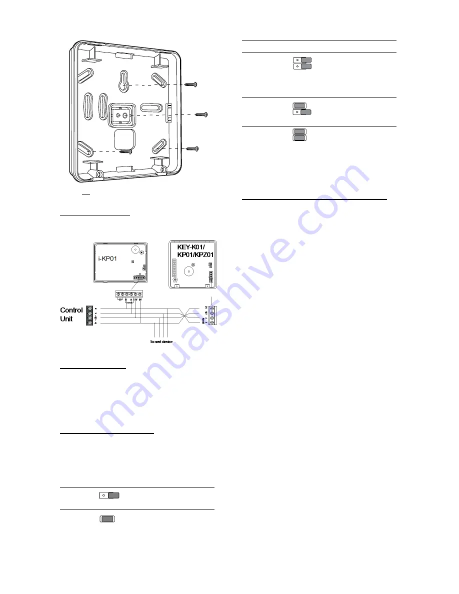
Figure 24 Screw KEY-K01/KP01/KPZ01 Back Box
to Wall
Connecting Keypads
Figure 25 shows the wiring connections at the
keypad and control unit.
Figure 25 Connecting a Keypad to the Bus
Keypad Addressing
The control unit assigns addresses to all devices
connected to the bus cable. If you wish, you can
start with one keypad connected to the bus,
address that keypad, and then attach and address
other devices at later times. See
“Initial Power Up”
on page 25 for instructions.
Backlight Control for i-KP01
You can control the appearance of the keypad
backlights and set/unset LEDs by fitting links over
the appropriate jumpers on the keypad PCB (see
Figure 8 for the position of the jumpers).
The jumpers have the following functions:
The set/unset LEDs
are disabled.
The set/unset LEDs
shows the setting
status of the system.
(Full set is the left
hand LED.) (see Note
below)
The key backlights are
disabled. They will
glow briefly for five
seconds when a user
presses a key.
The key backlights
glow all the time at
normal intensity.
The keypad backlights
glow all the time, extra
bright.
Note: To comply with PD6662:2010 for Grade 2
and 3, disable the ABCD LEDs. To comply with
EN50131-1:2006 at Grade 3: disable the ABCD
LEDs.
Backlight Control for KEY-K01/KP01/KPZ01
You can control the brightness of the keypad
backlights by fitting links over the BRIGHT jumper
on the keypad pcb (see 1b in Figure 12 or 6b in
Figure 14).
Jumper OFF
The keypad backlights glow at
normal intensity.
Jumper ON
The keypad backlights glow extra
bright.
To program whether the backlights are on or off
see below.
Programming Backlight, ABCD LEDs and
Navigation Key LEDs
You can set the function of the backlights in either
of two ways:
a) Use the
Installer Menu – Detectors/Devices –
Wired Keypads – Edit Keypad – (Keypad n) –
Backlight
option. See the
i-on Range Engineering
Guide
for more details.
b) Enter a local keypad programming mode (this
replaces the use of jumpers on the keypad PCB in
the i-kp01).
In addition, the local keypad programming mode
allows you to enable or disable the LEDs in the
ABCD keys and the Navigation key.
It is possible to enter the local keypad
programming mode when the keypad is not
connected to a control unit, but simply powered by
12VDC connected to the keypad bus terminal
(see Figures 12 and 14). If the keypad IS
connected to a control unit then make sure that
the control unit is in Installer Menu before entering
the keypad’s local programming mode.
Entering Local Programming Mode
1. Apply 12Vdc to the keypad.
2. Enter Installer Menu on the
control unit, if the
keypad is connected to a
ON
BRIGHT
BL
ABCD-ON
ON
BRIGHT
BL
ON
BRIGHT
BL
ABCD-ON
ON
BRIGHT
BL
ABCD-ON
ON
BRIGHT
BL
ON
BRIGHT
BL
ABCD-ON
ON
BRIGHT
BACKLIGHT
BACKLIGHT
BACKLIGHT
ABCD-ON
ON
BRIGHT
ON
BRIGHT
ABCD-ON
ON
BRIGHT
BACKLIGHT
BACKLIGHT
BACKLIGHT
ABCD-ON
ON
BRIGHT
ON
BRIGHT
ABCD-ON
ON
BRIGHT
BACKLIGHT
BACKLIGHT
BACKLIGHT
ABCD-ON
ON
BRIGHT
ON
BRIGHT
ABCD-ON


