11
2.5 Connections with a FlexPDU (Power Distribution Unit) Module (optional)
2.6 Connections with a HotSwap MBP Module (optional)
The HotSwap MBP module makes it possible to service or even replace the UPS without affecting the connected
loads (HotSwap function).
1. Connect the UPS powercord
(10)
to the AC
power source.
2. Connect the input cord of the FlexPDU
module
(48)
to the UPS outlet
(9)
. The cord
and the outlet are marked in red.
3. Connect the equipment to the outlets (45),
(46)
on the FlexPDU module. These outlets
differ, depending on the version of the
FlexPDU module.
EX 3000
EX 3000
1. Connect the input cord
(56)
of the
HotSwap MBP module to the AC power
source.
2. Connect the UPS input cord
(10)
to the
“UPS Input”
(55)
of the HotSwap MBP
module. This cord and the receptacle are
marked blue.
3. Connect the UPS outlet
(7)
to the “UPS
Output” cord
(54)
of the HotSwap MBP
module. This cord and the outlet are
marked red.
4. Connect the equipment to the outlets
(49)
on the HotSwap MBP module.
Caution:
Do not use UPS outlets (8)and (9) to
supply equipment because use of switch
(53) on the HotSwap MBP module would
cut supply to the equipment. It is advised
not to remove the protective film from
outlets (8) and (9).
86-86710-00EN A02 - Page 14
2. Installation
86-86710-00 A02 UM.indd 14
14/01/2009 10:56:24
HotSwap MBP module operation
UPS start-up with the HotSwap MBP module
1. Check that the UPS is correctly connected to the HotSwap MBP module.
2. Set switch
(53)
to the Normal position.
3. Start the UPS by pressing the ON/OFF button
(27)
on the UPS control panel.
The load is supplied by the UPS.
LED
(51)
“UPS ON - OK to switch” on the HotSwap MBP module goes ON.
HotSwap MBP module test
1. Set switch
(53)
to the Bypass position and check that the load is still supplied.
2. Set switch
(53)
back to the Normal position.
2.7 UPS Connection Without a FlexPDU or HotSwap MBP Module
Check that the indications on the name plate located on the back of the UPS correspond to the AC power source
and the true electrical consumption of the total load.
i
Note:
The UPS charges the battery as soon as it is connected to the AC power source, even if button
(27)
is not
pressed. Once the UPS is connected to the AC power source, eight hours of charging are required before the
battery can supply the rated backup time
i
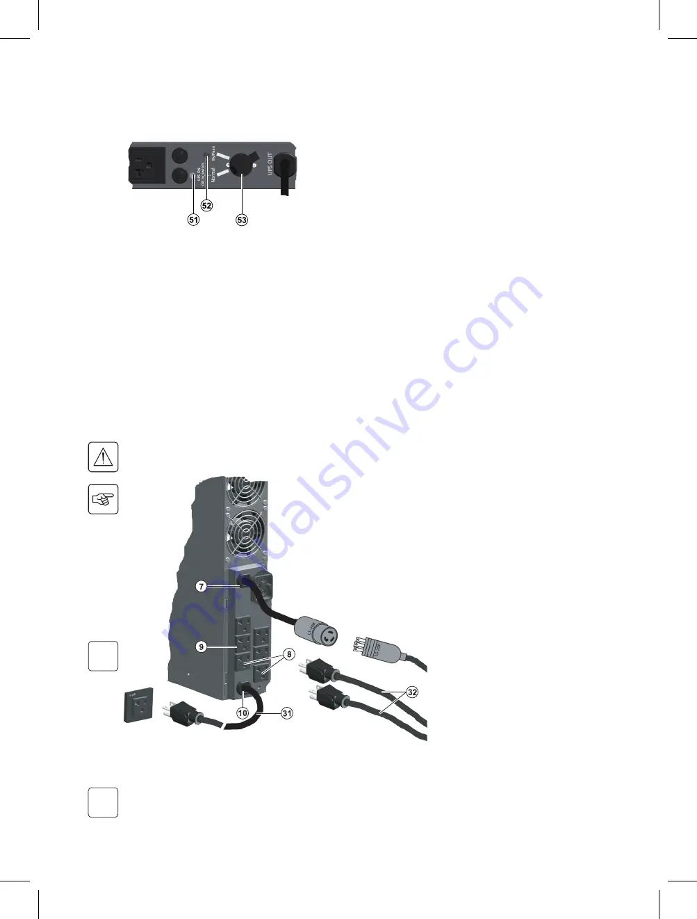
The HotSwap MBP module has a rotary
switch (53) with two positions:
Normal – the load is supplied by the UPS,
LED
(51)
is ON.
Bypass – the load is supplied directly by
the AC power source. LED
(52)
is
ON.
1. Connect the input cord
(31)
(100V 30A / or
20A on EX 2200) to the AC power source.
2. Connect the loads to the UPS.
It is preferable to connect the priority loads
to the four outlets marked
(9)
and the
non-priority loads to the two outlets
marked
(8)
that can be programmed.
Connect any high-power devices to the
20A (or 30A on EX 3000) outlet
(7)
as
shown at left for EX 2200.
To program shutdown of outlets
(8)
during operation on battery power and
thus optimise the available backup time,
the EATON communications software is
required.
86-86710-00EN A02 - Page 15
2. Installation
86-86710-00 A02 UM.indd 15
14/01/2009 10:56:26
Summary of Contents for EX Pulsar Series
Page 2: ...w P 86 86710 00...
Page 4: ......
Page 6: ......
Page 9: ...3 LED LED LED CFC HCFC UPS EATON EATON UPS EATON UPS...
Page 10: ...4...
Page 18: ...12 86 86710...
Page 22: ...16...
Page 33: ...www eaton com 86 86710 00 A02 86 86710 00 A02 UM indd 34 14 01 2009 10 56 53 www eaton com...
Page 34: ...w P 86 86710 00...
Page 36: ......
Page 38: ......
Page 42: ...4 86 86710 00...
Page 50: ...12 86 86710 00 This page left blank intentionally...
Page 54: ...16 4 4 4 86 86710 00 This page left blank intentionally...


