Installation manual
EPCT Fire series Fire Pump Controller
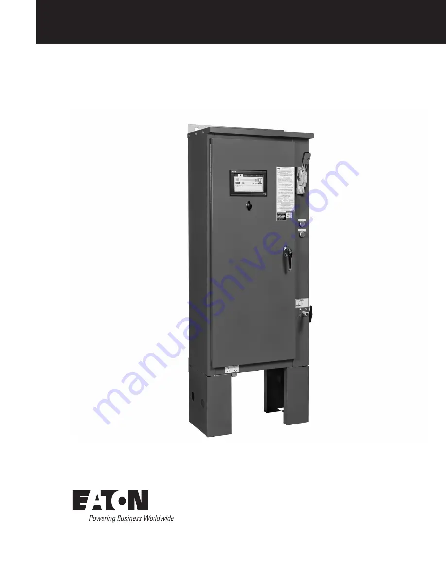
Page 1: ...Installation manual EPCT Fire series Fire Pump Controller...
Page 2: ...PARTICULAR PURPOSE OR MERCHANTABILITY OTHER THAN THOSE SPECIFICALLY SET OUT IN ANY EXISTING CONTRACT BETWEEN THE PARTIES ANY SUCH CONTRACT STATES THE ENTIRE OBLIGATION OF EATON THE CONTENTS OF THIS D...
Page 3: ...2 4 USB port 4 3 3 Power I O board 4 3 4 ATS board if equipped 4 3 5 Main isolating switch circuit interrupter 4 3 6 Contactor s 4 3 7 External pushbuttons 5 3 8 Transfer switch components 5 4 0 Opera...
Page 4: ...4 5 4 Power phase failure 4CR 10 4 5 5 Phase reversal 5CR 10 4 5 6 Pump run 6CR 10 5 0 Programming 11 5 1 Introduction 11 5 2 Navigation 11 5 3 Startup tab 12 5 3 1 Quick setup 12 5 3 2 Setup phase r...
Page 5: ...5 5 5 2 Service contact information 15 5 5 3 Factory contact information 15 5 6 Pressure settings tab 15 5 6 1 Start pressure 15 5 6 2 Stop pressure 15 5 6 3 Low pressure alarm 15 5 6 4 High pressure...
Page 6: ...0 6 2 Main contacts 20 6 3 ATS electrical control circuit 20 6 4 Mechanical transfer mechanism 20 6 5 ATS control board touchscreen display 21 6 5 1 Inputs 21 6 5 2 Outputs 21 6 5 3 Touchscreen displa...
Page 7: ...ture continued 34 Appendix F timer values tab menu structure 35 Appendix G a ATS settings tab menu structure 36 Appendix G b ATS settings tab menu structure continued 37 Appendix H a alarm setpoints t...
Page 8: ...ulations must be strictly observed in the installation operation and maintenance of this device CAUTION Completely read and understand the material presented in this document before attempting install...
Page 9: ...to the incoming AC power supply and motor wiring Install necessary conduit using proper methods and tools Recommend entry point is on the bottom of the enclosure Incoming AC line voltage is clearly ma...
Page 10: ...sed for reduced in rush current controllers only The AT will be factory set but will automatically adjust depending on the starting method that the controller is programmed to If it is found that more...
Page 11: ...Source 2 Disconnected Refer to the schematic diagram mounted on the inside of the controller door for all connection points specific to the controller 3 5 Main isolating switch circuit interrupter Th...
Page 12: ...tart of the pump motor Stop The stop pushbutton will initiate the stopping sequence of the fire pump motor Releasing the stop button will put the controller back into the automatic mode If a starting...
Page 13: ...r where when it expires the controller will exit the Welcome Screen to the Home tab and resume normal operation The three 3 buttons on this screen are CLOSE AND DISABLE WELCOME SCREEN CLOSE WELCOME SC...
Page 14: ...7 Operation EPCT Fire series Fire Pump Controller MN124016EN August 2019 www eaton com 4 2 1 2 Home Tab without an ATS Fig 1 HOME tab idle Fig 2 HOME tab pump running...
Page 15: ...Source 2 external disconnect handle and the motor The HOME tab will display the current system pressure reading along with the programmed Start and Stop setpoints At the bottom of the HOME tab is the...
Page 16: ...is in the Connected state the EPCT controller will initiate an automatic start sequence If programmed to automatically shutoff the pump when the input is in a Disconnected state and the RPT has elapse...
Page 17: ...ill delay all automatic starting means for the duration of the programmed timer 4 5 Output relays The primary control outputs of the EPCT controller are dry relay contacts These relays are comprised o...
Page 18: ...ingle phase start Enabled Disabled Auto shutdown Enabled Disabled Motor HP 0 9999 HP Nominal voltage 200 7200V Phases Single Phase Three Phase Description Range System Frequency 50Hz 60Hz CT Ratio 50...
Page 19: ...bled Dropout 100 999 Disabled Pickup Source 2 Under Frequency 0 100 Disabled Dropout 0 100 Disabled Pickup Description Range Source 2 Over Frequency 100 999 Disabled Dropout 100 999 Disabled Pickup In...
Page 20: ...s message history startup and configuration files to a USB device 5 4 Panel setup tab Refer to Appendix C for the menu structure of the Panel Setup tab 5 4 1 Language Nine 9 languages are offered as s...
Page 21: ...ion can then be used on other controllers that require the same configuration setup The configuration will not adjust functionality settings 5 4 21 Load configuration to USB A configuration file will...
Page 22: ...oint can be selected that will be recorded in the controller s history and displayed in the notification area if enabled 5 6 4 High pressure alarm A high pressure alarm point can be selected that will...
Page 23: ...to a known value typically 0 psi This value is then entered into the controller The system pressure is then increased to a higher known value which is also entered into the controller Calibrate Using...
Page 24: ...ller be equipped with an ATS the screen will provide the ability to have different setpoints for either Source 5 8 7 Frequency alarm settings This menu item allows the user to adjust frequency dropout...
Page 25: ...ory stats diag Tab history statistics diagnostics 5 10 1 Message history The EPCT controller will record a number of items in its memory to assist with troubleshooting of the system and or the fire pu...
Page 26: ...cer information The input status page will display the state of each input contact Pressing the input buttons the controller will override the state of that input for one minute If the button is depre...
Page 27: ...he ATS control board Energizing this relay will result in closure of the contact between terminals 72 73 on the ATS board Closing this contact will energize the ATS motor and the motor brake The motor...
Page 28: ...graphic on the display will show the Source 1 ATS contact closed and the Source 2 ATS contact open When in the Source 2 position the single line graphic on the display will show the Source 2 ATS conta...
Page 29: ...y start and run the generator at specific intervals The Weekly Timer is set by adjusting the day hour and minute of the desired weekly run time the length of time that this test shall be performed a t...
Page 30: ...ted at 8A 250VAC and 30 VDC and it includes two 2 pull apart six 6 pin terminal blocks 7 2 1 Programming i Refer to Appendix L 7 3 MODBUS Board It includes an eight 8 pole dip switch bank designed to...
Page 31: ...nu structure EPCT Fire series Fire Pump Controller MN124016EN August 2019 www eaton com Appendix A menu structure Note N Pressing the Back or Cancel button when available will return the screen to the...
Page 32: ...nu structure EPCT Fire series Fire Pump Controller MN124016EN August 2019 www eaton com Appendix B startup tab menu structure Note N Pressing the Back or Cancel button when available will return the s...
Page 33: ...nu structure EPCT Fire series Fire Pump Controller MN124016EN August 2019 www eaton com Appendix C a panel setup tab menu structure Note N Pressing the Back or Cancel button when available will return...
Page 34: ...re continued EPCT Fire series Fire Pump Controller MN124016EN August 2019 www eaton com Appendix C b panel setup tab menu structure continued Note N Pressing the Back or Cancel button when available w...
Page 35: ...re continued EPCT Fire series Fire Pump Controller MN124016EN August 2019 www eaton com Appendix C c panel setup tab menu structure continued Note N Pressing the Back or Cancel button when available w...
Page 36: ...re continued EPCT Fire series Fire Pump Controller MN124016EN August 2019 www eaton com Appendix C d panel setup tab menu structure continued Note N Pressing the Back or Cancel button when available w...
Page 37: ...re continued EPCT Fire series Fire Pump Controller MN124016EN August 2019 www eaton com Appendix C e panel setup tab menu structure continued Note N Pressing the Back or Cancel button when available w...
Page 38: ...nu structure EPCT Fire series Fire Pump Controller MN124016EN August 2019 www eaton com Appendix D help tab menu structure Note N Pressing the Back or Cancel button when available will return the scre...
Page 39: ...nu structure EPCT Fire series Fire Pump Controller MN124016EN August 2019 www eaton com Appendix E a pressure settings tab menu structure Note N Pressing the Back or Cancel button when available will...
Page 40: ...re continued EPCT Fire series Fire Pump Controller MN124016EN August 2019 www eaton com Appendix E b pressure settings tab menu structure continued Note N Pressing the Back or Cancel button when avail...
Page 41: ...re continued EPCT Fire series Fire Pump Controller MN124016EN August 2019 www eaton com Appendix E c pressure settings tab menu structure continued Note N Pressing the Back or Cancel button when avail...
Page 42: ...nu structure EPCT Fire series Fire Pump Controller MN124016EN August 2019 www eaton com Appendix F timer values tab menu structure Note N Pressing the Back or Cancel button when available will return...
Page 43: ...nu structure EPCT Fire series Fire Pump Controller MN124016EN August 2019 www eaton com Appendix G a ATS settings tab menu structure Note N Pressing the Back or Cancel button when available will retur...
Page 44: ...re continued EPCT Fire series Fire Pump Controller MN124016EN August 2019 www eaton com Appendix G b ATS settings tab menu structure continued Note N Pressing the Back or Cancel button when available...
Page 45: ...nu structure EPCT Fire series Fire Pump Controller MN124016EN August 2019 www eaton com Appendix H a alarm setpoints tab menu structure Note N Pressing the Back or Cancel button when available will re...
Page 46: ...re continued EPCT Fire series Fire Pump Controller MN124016EN August 2019 www eaton com Appendix H b alarm setpoints tab menu structure continued Note N Pressing the Back or Cancel button when availab...
Page 47: ...nu structure EPCT Fire series Fire Pump Controller MN124016EN August 2019 www eaton com Appendix I a inputs outputs tab menu structure Note N Pressing the Back or Cancel button when available will ret...
Page 48: ...re continued EPCT Fire series Fire Pump Controller MN124016EN August 2019 www eaton com Appendix I b inputs outputs tab menu structure continued Note N Pressing the Back or Cancel button when availabl...
Page 49: ...nu structure EPCT Fire series Fire Pump Controller MN124016EN August 2019 www eaton com Appendix J History stats diag Tab menu structure Note N Pressing the Back or Cancel button when available will r...
Page 50: ...nu structure EPCT Fire series Fire Pump Controller MN124016EN August 2019 www eaton com Appendix K Relay option board tab menu structure Note N Pressing the Back or Cancel button when available will r...
Page 51: ...nu structure EPCT Fire series Fire Pump Controller MN124016EN August 2019 www eaton com Appendix L a 4 20 mA device tab menu structure Note N Pressing the Back or Cancel button when available will ret...
Page 52: ...re continued EPCT Fire series Fire Pump Controller MN124016EN August 2019 www eaton com Appendix L b 4 20 mA device tab menu structure continued Note N Pressing the Back or Cancel button when availabl...
Page 53: ...nu structure EPCT Fire series Fire Pump Controller MN124016EN August 2019 www eaton com Appendix M MODBUS board tab menu structure Note N Pressing the Back or Cancel button when available will return...
Page 54: ...nu structure EPCT Fire series Fire Pump Controller MN124016EN August 2019 www eaton com Appendix N Supervisory alarm option board tab menu structure Note N Pressing the Back or Cancel button when avai...
Page 55: ...has failed MOTOR OVERLOAD The amperage draw has exceeded 125 of the programmed motor full load amps LOW RESERVOIR The controller has received a low reservoir signal HIGH RESERVOIR The controller has...
Page 56: ...tage measured by the controller has exceeded the programmed over voltage alarm set point for the normal source S2 OVER VOLTAGE The voltage measured by the controller has exceeded the programmed over v...
Page 57: ...rror There is no communication received from the display board 42 Frequency Error The frequency measurement is not receiving an accepted frequency 40 72Hz 43 Zero Cross Error The board did not receive...
Page 58: ...AX HP 25 30 40 60 75 1 14 1 0 Per CU AL 1 14 2 0 CU AL 40 50 75 100 100 1 4 4 0 Per CU 1 4 350MCM CU AL 75 75 150 200 200 1 3 350MCM Per CU AL 1 4 350MCM CU AL 100 125 200 250 300 2 3 0 250MCM Per CU...
Page 59: ...ay Burlington ON L7L 5Z1 Email chcfirepump eaton com Web www chfire com 2019 Eaton All Rights Reserved Printed in USA Publication No MN124016EN August 2019 Eaton is a registered trademark All trademar...