6
Montage- und Betriebsanleitung GuideLed 10011...11026 LED CG-S 40071860108 (F) www.eaton.com
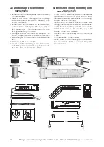
3.2 Wand-Halbeinbau 10012/11012
3.2 Semi-recessed wall mounting
10012/11012
20 m
10012
11012
30 m
• Ausschnitt (2) für eine ovale Geräte-Doppel-
dose bei 10012 und 11012 CG-S bzw. einfache
Gerätedose (Ø 60 mm, Höhe mind. 61 mm) bei
10013 und 11013 CG-S nach DIN 49073 (nicht
im Lieferumfang enthalten) erstellen
• Wandrahmen (3) an den jeweiligen 4 Bohrlö-
chern (1) an der Wand mit geeigneten Schrau-
ben befestigen
• Netzkabel anschließen, Versorgungsmodul (4)
in die Unterputzdose stecken
• Adresse am Versorgungsmodul (4) einstellen.
• Die LED-Anschlussleitung an der Rückwand
der Piktogrammscheibe Versorgungsmodul
(4) verbinden (2er Steckklemme).
Bipolarer
Anschluss der LEDs - auf eine Polung muss
nicht geachtet werden!!
• Piktogrammscheibe von oben auf den Wand-
rahmen aufschieben, bis Häckchen (6) einras-
tet.
• Zum Öffnen bzw. Lösen der Piktogramm-
scheibe mit einem dünnen Gegenstand
(z.B. Nagel) gegen das Häkchen (6) drücken.
• A cut-out (2) for the oval device double-junction
box for 10012 and 11012 CG-S or the simple
junction box (Ø 60 mm, height of mind. 61 mm)
for 10013 and 11013 CG-S acc. to DIN 49073
(not included in delivery).
• Fix the wall-frame (3) with suitable screws to
the wall at the 4 fixing holes (1).
• Connect the mains cable and put the supply
module (4) into the double-junction-box.
• Set the address on the supply module (4). Con-
nect the LED connection-cable, being back-
wards of the pictogram panel, to the supply
module, too.
Bipolar connection to LEDs - a
polarity has not be observed!!
• Slide the pictogram panel on the wall-frame
until it (6) snaps in.
• To open the pictogram panel push against the
fastening (6) with a suitable item (e. g. a nail).
13
14
18
13
1
2
3
4
5
6


