5
Mounting and Operating Instruction GuideLed 10011...11026 LED CG-S 40071860108 (F) www.eaton.com
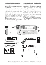
3.1 Wandmontage Aufputz
10011/11011 (Optional Einbau in
Leichtbauwänden)
3.1 Wall mounting, surface
10011/11011 (Optional recessed
mounting for lightweigh walls)
3. Montage / Maßbilder
20 m
10011/12
11011/12
11011
10011
30 m
3. Mounting /
dimensional drawings
Rückansicht Gehäuse und Piktogramm Back
view enclosure and pictogram
41
33
33 41
1
2
3
4
5
6
7
8
• Die Netzkabel durch die vorgesehene Kabelein-
führung (6) schieben
• Wandmontageadapter mit geeigneten Schrau-
ben an den Befestigungslöchern (4) an der
Wand fixieren (für Einbau der Leuchte dienen
Befestigungslöcher 2)
• Netzkabel an das Versorgungsgerät an den
Klemmen L und N anschließen (optional an die
Steckklemme 5)
• Adresse am Versorgungsmodul (7) einstellen
• LED-Anschlussleitung an der Rückwand der
Piktogrammscheibe (8) mit dem Versorgungs-
modul V-CG-SLS 28 (7) verbinden, (2er Steck-
klemme).
Bipolarer Anschluss der LEDs - auf
eine Polung muss nicht geachtet werden!!
• Piktogrammscheibe von oben auf die Rück-
wand an den Steckfassungen (3) einschieben
• Zum Öffnen bzw. Lösen der Piktogrammschei-
be das Häkchen (1) zur Seite schieben.
• Feed mains cable through cable entries (6)
• Fix mounting adapter to wall with suitable
screws through fixing holes (4). (For recessed
wall mounting, use fixing holes 2)
• Connect mains cable to supply module at termi-
nals L and N (optional to terminal 5)
• Set the address on supply module (7)
• Connect the LED connection-cable (8),to the
supply module V-CG-SLS 28 (7).
Bipolar con-
nection to LEDs - a polarity has not be ob-
served
• Slide the pictogram panel on wall mounting ad-
apter via plug-in sockets (3)
• To open the pictogram panel, push against the
fastening (1).


