background image


UPS 40 – 160 kVA, 400V 50/60 Hz output  

User’s and Installation Guide 

1023294 
Revision  C

29

5.1  XSlot communication

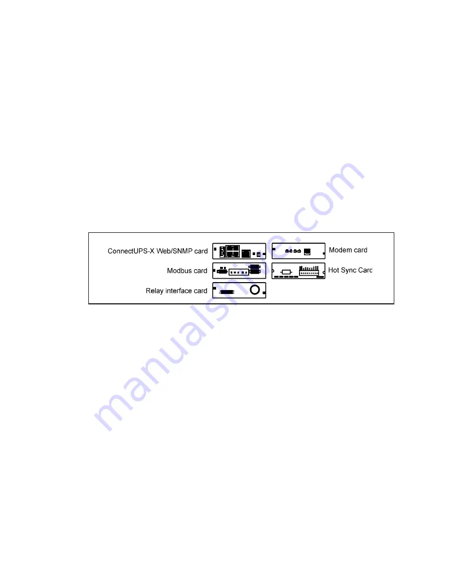
The UPS is compatible with the following XSlot cards. Refer to the manual supplied with the 
X-Slot card for user instructions.

• 

ConnectUPS -X Web/SNMP/Hub Card

 - provides remote monitoring through a Web brows-

er interface, e-mail, and a network management system (NMS) using SNMP; connects to a 
twisted-pair Ethernet (10/100BaseT) network. It has a built-in switching hub that allows 
three additional network devices to be connected to the network without the requirement 
of additional network drops.

• 

Relay Interface Card (AS/400)

 - has isolated dry contact relay outputs for UPS status: Util-

ity failure, Low battery, UPS alarm/OK, or On bypass when interfacing with IBM® AS/400 
computers, other relay connected computers, and industrial applications.

• 

Modbus Card

 - provides direct integration of UPS information to a Building Management 

System (BMS) using the Modbus RTU protocol.

• 

Modem Card

 - provides remote notification and monitoring using modem communication 

directly to 7/24 monitoring centres. Provided as part of the premium service package to 
customers.

• 

Hot Sync Card

 - the parallel interface card

Figure 21.

  Optional XSlot Cards.

Facility planners or customer must provide LAN and telephone drops, for use with XSlot 
connectivity cards. 

5.1.1  Wiring installation for XSlot connections

It is recommended that the control cables and power cables be installed on separate trays. 
Where control cables will cross power cables make sure they are arranged at an angle as near to 
90 degrees as possible. 

All control cables shall preferably be shielded. If the shield is grounded, this shall take place on 
only one end of the cable. 

The installation procedure is following:
1. 

If not already installed, install LAN and control wire drops.

2. 

Unfasten front door latch and swing door open.

3. 

Remove XSlot wire entry conduit landing plate to drill or punch conduit holes.

4. 

Reinstall conduit landing plate and install conduit.

5. 

Route and install LAN and other control cables to appropriate X-Slot cards.

6. 

Close door and secure with latch.

7. 

Refer to the manual supplied with the XSlot card for user instructions

Summary of Contents for 40 kVA

Page 1: ...User s and Installation Guide UPS 40 160 kVA 400V 50 60 Hz output...

Page 2: ...t of the publisher and may not be reproduced even extracts unless permission granted Every care has been taken to ensure the accuracy of the information contained in this manual but no liability can b...

Page 3: ...ferrite rings 19 4 2 2 Installing ferrite clip for battery breaker 19 4 3 Battery cabinets 19 4 3 1 Integral battery cabinet installation procedure 21 4 3 2 Integral battery cabinet electrical connect...

Page 4: ...to normal mode 48 8 Maintaining the UPS System 49 8 1 General 49 8 2 Important Safety Instructions 49 8 3 Performing Preventive Maintenance 50 8 3 1 DAILY Maintenance 50 8 3 2 MONTHLY Maintenance 50...

Page 5: ...present 1 1 Audience The intended audiences of this manual are people who plan the installation install commission and use or service the UPS The manual provides guidelines to check delivery installin...

Page 6: ...ws excluding connectivity plates Failure to recognise the electrical hazards could prove fatal 1 4 Environment The UPS must be installed according to the recommendations in this manual Under no circum...

Page 7: ...e the adverse effect on production equipment due to unexpected power problems The UPS system continually monitors incoming electrical power and removes the surges spikes sags and other irregularities...

Page 8: ...itors that the load never crashes because of bad or defected battery The main cause for corrosion is current flowing through battery The more current going through battery the shorter the battery life...

Page 9: ...er at all times Its unique digital design eliminates the system level single point of failure inherent in traditional parallel UPS modules and exponentially increases the reliability of the overall sy...

Page 10: ...unit Set the pallet on a firm level surface allowing a minimum clearance of 3m on each side for removing the cabinet from the pallet Note If the UPS is not immediately installed the following must be...

Page 11: ...skids on the bottom of the unit 2 Unfasten front door latch and swing door open 3 If the levelling feet are not fully retracted turn the levelling feet until they are retracted 4 Remove bolts and ship...

Page 12: ...must be informed within 7 days of receipt of the equipment The packing materials and indicators should be stored for further investigation 3 3 Delivery check The UPS is delivered with the following i...

Page 13: ...r inch by six inch wood supports 1 Unfasten front door latch and swing doors open 2 Remove doors Remove the retaining screw located inside each door at the bottom hinge pivot point then lift the door...

Page 14: ...s out from under the battery cabinet Please discard or recycle them in a responsible manner Note CABINET MAY FALL Do not loosen the hardware attaching the side or front supports to the cabinet base or...

Page 15: ...p or bottom of the cabinet see dimensional drawings with connections made to easily accessible terminals 1 If not already open unfasten front door latch and swing door open 2 Slide air filter up and r...

Page 16: ...ng The disconnect device shall have a contact separation of at least 3 mm The UPS has automatic backfeed isolation but for extra safety a warning label can be added on all primary power isolators inst...

Page 17: ...current capacity are needed if the external battery cabinets or racks are installed with a distance from the UPS 11 When all wiring is complete and the UPS system is connected to the facility power an...

Page 18: ...0 kVA Cables with copper conductor temp 70 C PCV insulation and installation method C UPS rating Rectifier input Bypass input Load PE Battery Fusing Cable Fusing Cable Cable I nom Cable Cable 40 kVA 3...

Page 19: ...inet as possible 4 2 2 Installing ferrite clip for battery breaker The ferrite clips are delivered and meant for control wires between the UPS and the battery breaker Place the control wires to the no...

Page 20: ...ound battery cabinets Remove watches rings or other metal objects Use tools with insulated handles Wear rubber gloves and boots Do not lay tools or metal parts on top of batteries or battery cabinets...

Page 21: ...anger brackets from the right hand side of the battery cabinet Save cover screws and brackets for later reuse 6 Remove the knockout plug on the bottom left side of the UPS cabinet inside panel Figure...

Page 22: ...e lower right hand battery tray through the access hole in the side panel of the UPS and attach to the ground stud in the UPS cabinet Hardware is provided on each ground stud 14 If installing addition...

Page 23: ...ng more than one battery cabinet the battery cabinet adjacent to the UPS will be the only cabinet directly connected to the UPS Figure 15 General battery cabinet wiring installation Use this procedure...

Page 24: ...battery breaker or disconnect 12 Battery URV Aux contacts are rated as follows 240VAC 15A 125VDC 0 3A 250VDC 0 15A Table 3 TB1 interface connections in the battery cabinet Figure 17 TB1 interface wiri...

Page 25: ...should be installed both at the UPS cabinet end to improve the EMC according to EU directives Use this procedure to install a separately located battery cabinet 1 Make sure that the UPS is properly i...

Page 26: ...the hanger brackets and align with the front and rear of the battery cabinet 16 If not already secured secure the side panel at the bottom using M4 hex head screws previously removed 4 3 4 Separate B...

Page 27: ...y reinstalling safety shields and closing and latching the doors A battery disconnect switch is recommended and may be required by local codes when batteries are separately located The battery disconn...

Page 28: ...tion interface The UPS has a standard factory installed XSlot communication bay with two slots An optional second bay is available providing two additional slots Communications XSlot option cards are...

Page 29: ...mote notification and monitoring using modem communication directly to 7 24 monitoring centres Provided as part of the premium service package to customers Hot Sync Card the parallel interface card Fi...

Page 30: ...ious user groups to select the most compelling and useful view for their specific needs For information on installation and operation refer to the Software Suite CD ROM shipped with the UPS The LanSaf...

Page 31: ...ally Open contact closes when UPS is on bypass 4 On Bypass Relay Return 5 Alarm Relay NC General purpose Normally Open and Normally Closed relay contacts 6 Alarm Relay Com 7 Alarm Relay NO 8 Alarm Rel...

Page 32: ...nal blocks at the top of the UPS cabinet 4 Locate the appropriate terminals 5 If battery cabinets are installed attached to the UPS cabinet proceed to step 6 if battery cabinets are installed separate...

Page 33: ...g door open 4 Remove screws securing internal panel covering TB1 and TB2 terminal blocks at the top of the UPS cabinet 5 If installing interface wiring from the bottom of the cabinet proceed to step 6...

Page 34: ...ions wire additional stations in parallel with the first Remote EPO 12 If required install wiring from the Remote EPO station to trip circuitry of upstream protective devices A normally open contact i...

Page 35: ...ical column of status indicators 3 When the unit powers up the screen displays the Powerware logo To advance to the Main menu and Mimic screen press any Control Panel pushbutton once After approximate...

Page 36: ...area to help you monitor and control UPS operation The following menus and options are available EVENTS Displays the list of Active System Events and a historical log of system events METERS Displays...

Page 37: ...n Menu bar to display the Unit Meter screens To scroll through the meter screens press the UP or DOWN pushbuttons on the menu bar The current UPS readings are displayed in the information area of the...

Page 38: ...Controls screen toggles the charger function On and Off The PM pushbutton switch toggles the Power Module function On and Off 6 2 4 Setup screen Press the SETUP pushbutton on the Main Menu bar to dis...

Page 39: ...is used to change and save the settings for the serial communication ports The COM port number selected from the Serial Port Setup screen will be displayed If the changes are not wanted the ABORT pus...

Page 40: ...notices Some notices may be accompanied by an audible horn To silence the horn press any Control Panel pushbutton once The indicator may be flashing while other indicators are illuminated The indicat...

Page 41: ...er turns on and the UPS transfers to Normal mode The status indicator on the UPS Control Panel indicates the UPS is in Bypass mode If Auto Bypass is not enabled the UPS output remains off until the UP...

Page 42: ...rt the Power Module without transferring the critical load to normal perform the following procedure 1 Close the UPS input feeder circuit breaker 2 Close UPS Bypass input feeder circuit breaker 3 Obse...

Page 43: ...processor remains on and an alarm sounds 3 The UPS is now operating in the bypass mode and the BYPASS status indicator is illuminated The Power Module PM status indicates READY System is now on bypas...

Page 44: ...Load Shutdown To perform maintenance or service on the critical load shut down power to the load by performing the following procedure 1 Turn off all equipment that is being powered by the UPS 2 Perf...

Page 45: ...output and bypass backfeed contactors open the battery breaker or disconnect is tripped and the Power Module is turned off Note Do not attempt to restart the system after Load Off until the cause of...

Page 46: ...e UPS after using the REPO pushbutton reset the REPO switch and then follow the procedure in paragraphs 7 1 or 7 2 7 11 Using Mechanical Bypass Switch 40 80 kVA The operation of the integral MBS is al...

Page 47: ...g 2 Perform transfer from normal mode to bypass mode as described in paragraph 7 4 Remember to verify the transfer before proceeding the next step 3 Turn ON the S3 switch to bypass UPS 4 Turn OFF the...

Page 48: ...2 Turn ON rectifier switch to connect rectifier input to UPS 3 Turn ON S2 switch to connect bypass input to UPS 4 Perform UPS start up procedure bypass mode contained in paragraph 7 2 5 Turn ON S4 swi...

Page 49: ...ive panels removed Do not make any assumptions about the electrical state of any cabinet in the UPS system Since each battery string is an energy source in itself opening the Battery Circuit Breaker d...

Page 50: ...ed or the Normal status indicator is not illuminated contact your service representative 8 3 2 MONTHLY Maintenance Perform the following steps monthly 1 Monitor system parameters from the Control Pane...

Page 51: ...ollowing bullets indicate standard keyboard characters To use a key combination hold down the Escape key and press the indicated letter key 8 4 1 Display UPS Control Panel When this function is invoke...

Page 52: ...2 digits SS Second 2 digits hh Hundredths of Second 2 digits KYWD Keyword ALARM NOTICE COMMAND or STATUS System Diagnostic Information CR Carriage Return Character ASCII 13 LF Line Feed ASCII 10 An a...

Page 53: ...m bypass This can be used for service or test purposes The available SPM tie cabinets have the following maximum power ratings SPM type UPS rating SPM bypass rating SPM voltage rating SPM9390 80kVA 4U...

Page 54: ...UPS 40 160 kVA 400 V 50 60 Hz output User s and Installation Guide 1023294 Revision C 54 Figure 36 Wiring diagram for HotSync Parallel UPS system up to 4 UPS with SPM...

Page 55: ...240 mm 150 mm 400 A 320 kVA 2 x 150 mm 150 mm 2 x 250 A or 500 A 400 kVA 2 x 185 mm 185 mm 630 A 480 kVA 2 x 300 mm 300 mm 800 A 640 kVA Busbar System 1000 A Table 7 Recommended cables and fuses for t...

Page 56: ...ons for 120 160 kVATie cabinet Warning Some components inside the cabinet contain high voltage which can injure or kill per sonnel or damage equipment All operations inside the cabinet must be carried...

Page 57: ...ready open unfasten front door latch and swing door open 2 Remove the door by opening a screw from the bottom hinge 3 Place the door to its correct position 4 Remove the switches S11 S21 S31 and the s...

Page 58: ...either top or bottom of the cabinet 8 System input cables L1 L2 L3 and N should be connected next to the fuses S11 S21 S31 9 PE cables should be connected to terminal X1 at the bottom of the cabinet...

Page 59: ...N cable wiring diagram Terminal J3 Name Description 1 Alarm Programmable UPS alarm Activated by a remote dry contact closure 2 Alarm Rtn 3 Alarm Relay NC Normally closed contact opens when UPS is on b...

Page 60: ...umper J7 The default jumper setting without termination resistor is J7 Pin 2 3 Place the the jumper J7 to correct setting the first and last UPS modules should have the CAN bus termination resistor en...

Page 61: ...for parallel UPS system Building Alarm Pull Chain Wiring Terminations From UPS 1 To UPS 2 To UPS 3 If installed To UPS 4 If installed TB2 1 BA 2 TB2 1 BA 2 TB2 1 BA 2 TB2 1 BA 2 TB2 2 Rtn TB2 2 Rtn T...

Page 62: ...r disposal contact your local collecting recycling reuse or hazardous waste center and follow the local legislation These symbols indicate on a product Use proper local collecting centers meeting loca...

Page 63: ...160 kVA 400V 50 60 Hz output User s and Installation Guide 1023294 Revision C 63 11 Dimensional drawings Figure 44 UPS cabinet dimensions 40 80 kVA Figure 45 UPS cabinet top and bottom dimensions 40...

Page 64: ...UPS 40 160 kVA 400 V 50 60 Hz output User s and Installation Guide 1023294 Revision C 64 Figure 46 UPS cabinet dimensions 100 160 kVA Figure 47 UPS cabinet top and bottom dimensions 100 160 kVA...

Page 65: ...UPS 40 160 kVA 400V 50 60 Hz output User s and Installation Guide 1023294 Revision C 65 Figure 48 Large battery cabinet dimensions Figure 49 Large battery cabinet top and bottom dimensions...

Page 66: ...V 50 60 Hz output User s and Installation Guide 1023294 Revision C 66 Figure 50 Small battery cabinet dimensions and empty space for batteries Figure 51 Small battery cabinet side top cabling and loa...

Page 67: ...UPS 40 160 kVA 400V 50 60 Hz output User s and Installation Guide 1023294 Revision C 67 Figure 52 HotSync System Parallel Module SPM9390 80 kVA 4UPS dimensions...

Page 68: ...12 3 Mechanical configuration UPS 40 kVA 60 80 kVA 100 120 kVA 160 kVA Dimensions Width Depth Height 519 mm 808 mm 1879 mm 944 mm 808 mm 1879 mm Weight UPS Small BAT 38 Ah Small BAT 200WPC Large BAT...

Page 69: ...0 kVA 60 80 kVA 100 120 kVA 160 kVA Active power 36 kW 54 72 kW 90 108 kW 144 kW Voltage 220 380V 230 400V 240 415V user selectable Frequency 50 or 60 Hz user selectable Voltage regulation 1 10 to 100...

Page 70: ...from a failure if the installation commissioning repair alternation or ambient conditions of the equipment do not fulfil the requirements specified in the docu mentation delivered with the unit and ot...

Reviews: