background image

2

5

25

STRUCTURE OF HOT WATER 
PRODUCTION SYSTEM


In the system of hot water production there are 2 main elements: heat-exchange unit (point 

1) and water receiving tank (point 2) connected by pipes.


Heat-exchange unit is a rectangular tank with a volume of 3,5 liters. Its function is heating 

up of water by receiving heat of the furnace. The heat-exchange unit is attached directly to the side 

wall of the furnace. There are one inch threaded joints (points 3 and 4) on the top and on the bottom of 

the heat-exchange unit that connect pipe-lines to the side-mounted tank.

Heat-exchange unit is a structural section of the furnace. When the furnace is heated up, it is not 

allowed to fill up the system if there is no water in the water level gauge of the side-mounted 

water receiving tank.

Constant exploitation of the system without water is not permitted because it leads to short life of 

a furnace.


Side-mounted water receiving tank is a rectangular, cylindrical or di erent shape reservoir 

(shape  and  dimensions  can  vary  based  on  customers  wishes  and  technical  peculiarities  of  the 

installation site). At the top of a tank there is a tank fillet pipe (point 5) which is needed to fill the system 

with water, with a hermetic lid (point 6) and one inch threaded joint (point 7) for steam removal from 

indoor space. There are one inch threaded inlet and outlet joints (points 8 and 9) at the bottom of a 

tank.  The  hot  water  faucet  (point  10)  is  on  the  front  wall  of  a  tank.  All  water  receiving  tanks  are 

equipped with water level gauges which allow monitoring water level while in operation.

Fill the tank with water not exceeding upper point of the water level gauge.

The heat-exchange unit and water receiving tank are connected by metal pipes (points 11 and 12) one 

inch in diameter. There is a T-tube (point 13) with connected discharge pipe on the bottom tube which 

allows discharging water system via faucet (point 14) in wintertime.

In circumstances when the distance between heat-exchange unit and water receiving tank is 

less than 1 metre, when water level lowers while in use or when the furnace burns for more than 3 

hours, water can start boiling. Water boiling goes along with insignificant noise.

To prevent boiling add some cold water in the system (if water level lowers when in use).

Choose water receiving tank based on assumption that there's should be 15 litres per person plus 10 

litres to steam the bath besom.

Summary of Contents for ANAPA

Page 1: ...ANAPA SOCHI GELENDZHIK INSTALLATION AND MAINTENANCE ...

Page 2: ...m room you ll get the optimum correlation between the temperature and air humidity microclimate which will be perfect for you Make your own Russian banya Banya with its intrinsic pleasant warmth and easy steam For correctandsafefurnace exploitation readthisinstructioncarefully Enjoy your bath EasySteam company This document is protected by the Copyright Act by the International Copyright Act and I...

Page 3: ...ade of natural stones Protective heat retaining shield made of bricks Hot water production system Structure of hot water production system Operation of hot water production system Installaton of hot water production system Overall dimentions of furnace Technical characteristics Configuration Guarantee obligations Equipment certificate Troubleshooting guide 13 Construction scheme of foundation 16 Ass...

Page 4: ...1 04 PRODUCT PURPOSE In order to use the furnace for other purposes you need to have a written permission of the manufacturer If the furnace is used for commercial purposes as well as if the furnace is burning for more than 10 hours all guarantee obligations would be declared null and void and manufacturer will notbeheldliablefor any potentialadverseconsequences ...

Page 5: ...g unit Protective heat retaining shield Dispensing unit water supply Ash box When the gas equipment is installed the heat control shutter and the main chimney shouldn t be installed 3 Furnace body 1 Convection canals 2 4 Flame spreader 5 6 7 8 10 12 9 Fuel channel 13 14 15 Boiler grate 11 Cleanout port 16 Air governor 17 ...

Page 6: ...he flame spreader is working the most flames are staying in the furnace heating it up and only combustion gases end up in the chimney In order to equally distribute the load of massive heater s filling the heater s bottom is made semicircular that also let s to increase the heating area and to prevent the bottom elevated temperature deformation Maintenance of the equipment is done through the steam p...

Page 7: ...port point 16 The cleanout port serves to clean and examine manufacturing clearances between the heater and the furnace body Examine manufacturing clearances not less than once a year or when there is a di culty of a chimney draft In case if there is a lot of soot in the clearances clear it o with a flexible brush for smoke pipes pic 1 In order to get to cleanout port ease o the cap nut on the lid ...

Page 8: ...e protective heat resisting shield in the front of the furnace should be as high as the full height oftheroom pic 4 When developing your banyas project and installing the furnace it is NECESSARY to ensure that all fire safety standards mentioned in the Code of Practice CP 112 13330 2011 Fire safety of buildings and facilities and CP 7 13130 2013 Heating ventilation and conditioning Fire safety requ...

Page 9: ...s In order to avoid damaging the furnace it is not recommended to make a monolithic type laying of stones You should always leave some space between the stones Total mass of the filling shouldn texceedthemaximumvalue mentionedinthismanual To be able to use natural or liquefied gas as fuel burner units of the ГГУ or САБК ТБ series were installed at the factory Pic 2 Burner units appearance Burner uni...

Page 10: ... starts and high temperature gases go up through manufacturing clearances between the heater and the furnace body as well as through the main chimney and engulf the heater in flames At the highest point high temperature gases run against the top of the furnace and form a circle around the heater in so doing enhancing the heating up of the inner filling Oxygen that is essential for high temperature c...

Page 11: ...me of which is equal to one of the dispensing unit transfor mationinto thesteamtakes no longerthan5 seconds Decrease of walls temperature in the mode intensive heating up of the heater is a continuous processwhichdoesn tleadto theircomplete cool down If the temperature in the sweating room drops lower than 60 70 degrees in case of continuous exploitation you should switch the furnace to the intens...

Page 12: ...ments it is possible to combine two founda tions In this case draw special attention to the installation of reinforcement cage and foundations connecting node Foundations width and length are determined in accordance with overall dimensions of the furnace plus manufacturing clearance which takes into account the thickness of the protective shield and all essential clearances In some cases it is ne...

Page 13: ...1 13 Pic 3 Construction scheme of foundation Moisture penetration barrier Wooden formwork Reinforced concrete foundation 150 mm gravel pad 150 mm sand pad CONSTRUCTION SCHEME OF FUNDATION ...

Page 14: ... than12hours For a time of solidification up to 22 days the foundation should be covered with polyethylene sheetingand ifnecessary irrigatedwithwater inorder to avoid suddenwater evaporation SIZE CALCULATIONS FO THE FOUNDATION Width mm b 2xb 2хb 2хe where f ac оp shd E is the thickness of the protective heat retaining shield natural stone 40 60 mm brick 65 120 mm shd b is the width of the furnace f...

Page 15: ...ricks helps to fully dehumidify sweating and washing rooms Toinstall thefurnacecorrectly it isrecommendedto followrequirementsof theactualmanual Pic 4 The example of the furnace with a natural stone cover Install the furnace foundation ref section Furnace foundation Saw up a passage for the combustion flue Theminimumdistancebetweenthecoverand inflammablesurfacesis500mm Install the furnace on the pre...

Page 16: ...asySteam s veneers are only made of soapstone serpentine marble or pyroxenite tiles and fastening element without any adhesives Each tile has its own place in the cover The wall by the firebox is considered as the front of the cover There is a number of tier a front back indication and an orientation arrow on each tile For covers with columns in the corners there is an information on between which ...

Page 17: ...ue cover Install the tiles of the third tier Install metal plates in notches in tiles ends 4 3 2 left 2 right 2 back 3 left 3 right 3 back Install the tiles of the forth tier Install metal plates in notches in tiles ends Place the top lid upper plates on ribs of metal plates 6 5 4 left 4 right 4 back 3 front 4 front 1 17 ...

Page 18: ...E HEAT RETAINING SHIELD MADE OF BRICKS Pic 5 The example of the furnace with a separately standing chimney Following types of chimneys shall be applied Single circuit stainless chimney with a brick cover Sandwich type chimney Solid ceramic furnace brick LODE Latvia Solid ceramic furnace brick Gdjel Solid ceramic furnace brick Kirovo Chepetskiy Solid ceramic furnace brick Vitebskiy 1 factory worksh...

Page 19: ... in order to achieve maximum convection e ect Minimum recommended area for lower convection doors is 500 cm and 600 cm for upper ones The protective heat shield in the front of the furnace should be as high as the full height of the room Around and across the heat control shutter stem it is required to make a 5 mm manufacturing air clearance to compensate temperature expansions To cover the combus...

Page 20: ...Pic 6 Example of the furnace with a brick cover which heats up both resting and sweating rooms 1 20 ...

Page 21: ...with not more than 120 kg of stones or 1 layer of bricks without binding materials clay solution Because covering sheet isn t a load bearing element it is not allowed to lay bricks on it in order to coverthechimney If the furnace is installed according to this design economizer should be installed as the first section of a chimney If the furnace is installed with a separately standing chimney it is...

Page 22: ...1 22 Pic 8 Example of furnace with a brick cover and a covering sheet Pic 9 Example of furnace with a brick cover and a separately standing chimney ...

Page 23: ...uts by use of 2 5 mm hex nut wrench 2 Screw up the left corner from the inside of the frame with 3 M4 nuts by use of 2 5 mm hex nut wrench 3 Screw up the right corner from the inside of the frame with 3 M4 nuts by use of 2 5 mm hex nut wrench ASSEMBLY SCHEME FOR THE VENEER ...

Page 24: ...et joint Water receiving tank Water dump faucet Connecting pipe 1 Outlet joint 9 T tube 13 Drain faucet 14 8 2 10 3 12 Steam outlet joint 7 Tank filler pipe 5 Outlet joint 4 Connecting pipe 11 Tanks lid 6 24 HOT WATER PRODUCTION SYSTEM ...

Page 25: ...ite At the top of a tank there is a tank fillet pipe point 5 which is needed to fill the system with water with a hermetic lid point 6 and one inch threaded joint point 7 for steam removal from indoor space There are one inch threaded inlet and outlet joints points 8 and 9 at the bottom of a tank The hot water faucet point 10 is on the front wall of a tank All water receiving tanks are equipped with...

Page 26: ...ed time of water heating to the temperature of 80 degrees is between two and three hours and depends on layout of heat exchange unit and water receiving tank connection as well as on their physical distance In case if there is a big distance between heat exchange unit and water receiving tank or when thegeometryofinlet pipes iscomplex cutthelow power circulatingpump into thesystem The process of s...

Page 27: ...nkto heat exchangeunit Eachadditionalbend ofconnectingpipes negativelya ecttheprocessofcirculation Connect water receiving tank and heat exchange unit avoiding unnecessary bends of connecting pipes You should only use high temperature materials flax fiber as a seal for threaded connection joints of the heat exchange unit To remove the steam from indoor space connect the steam outlet joint to a pipe ...

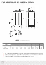
Page 28: ...ns could slightly di er from ones mentioned in this table Chimney diameter of standardmodelsoffurnaces is120 mm for Gelendzhikfurnace 150mm Furnace Dimentions мм А B C D E F G H Pic 10 Furnace dimentions Anapa Sochi Gelendzhik 405 435 435 465 535 535 805 955 1055 200 200 200 530 530 610 420 420 450 890 1040 1140 185 185 250 А B C F G E D H ...

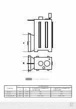
Page 29: ...K H with ГГУ or САБК ТБ burner unit 450 520 520 370 390 390 520 520 520 520 390 390 480 390 J K 1 29 Furnace Anapa Sochi Gelendzhik Dimentions мм J with ГГУ or САБК ТБ burnerunit Pic 11 Furnace dimentions ...

Page 30: ...ussian banyas mode winter summer Maximum log length Amount of consumable logs Size of a glass in the door W H Fuel type Anapa Sochi Gelendzhik up to 16 up to 22 up to 35 420 420 450 890 1040 1140 730 730 810 4 6 mm stainless heat resistant steel steel heat resistant glass ceramic stainless steel closed internal heater built in unit to the lower part yes yes yes yes yes bent welded structure 120 mm...

Page 31: ...packaging All component parts are wrapped in a soft packaging and placed inside the furnace Wood burning furnace with a built in steam generating unit Door Ash box Boiler grate Dispensing unit water supply Lid of the dispensing unit Lid of the heater Installation and operation manual product certificate Componentparts 1 pce 1 31 1 pce 1 pce 1 pce 1 pce 1 pce 1 pce 1 copy ...

Page 32: ...nty liabilities upon any of the following Inappropriate use of the furnace Commercial use of the furnace Furnace exploitation with a natural stones veneer from another manufacturer laying of the Expiration of a warranty 2 3 4 Independent repair or changes in the engineering design of the furnace Installation of burner units unauthorized by manufacturer 5 6 7 Installation of gas equipment in the fu...

Page 33: ...ons Conclusion the product is qualified as suitable for exploitation Quality control department check mark The test was performed by position held surname first name and patronymic signature 202 year month date Serial 1 33 Modification standart М2 ad door to the heater Material AISI 430 AISI 321 Thickness 4 6 mm Fuel wood gas wood gas standard equipment ГГУ burner units САБК burner units approved КО ...

Page 34: ...n the system boils Water in the heat exchange unit boils but water in the water receiving tank is still cold Air deficiency in the heater Di culty of a chimney draft Di culty of a chimney draft Insu cient leak tightness of the chimney Chimneys deterioration Draft di culty Back pressure valve is clogged Foreign object in the back pressure valve Poor quality stones Old stones Dysfunction of the steam...

Page 35: ......

Page 36: ......

Reviews: