background image

20 

The space between the two rubbers is adjusted in working state. In stand-by 

  state, the unbalance of space between the two rubber rollers is produced by the screw   

pitch of the stroke adjustment structure, which does not affect normal operation. If   
the quality of lamination is affected, check and adjust according to the following steps: 


·

 Open the right and left cabinet covers; 

· 

Check if the left and right pressure adjustment pedestals are loosened. If   
so, adjust the pressure adjustment pedestals and tighten them;


·

  Check to see if the longitudinal bevel gears on both sides are loose. If the 

left is loose, open the gear and take down the screw of pressure-regulat- 
ing support. Tighten the screw at the gear top with a wrench after tilt   
the transverse bevel gear. Then fix the parts in where they were. If the   
right longitudinal bevel gear is loose, it is not necessary to dismantle   
the transverse bevel gear. The other checking steps are the same as for 
the left side. 


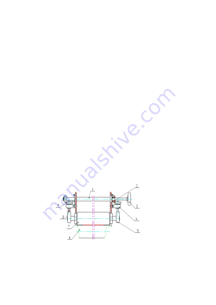
· How to adjust the space between the two rollers: ( Please see Figure 13 ) 

1)


Place  a  piece  of  photo-printing paper  between  the two  rubber  rollers with  a  moderate 
length  (150mm  narrower  on  both  sides  than  the  film).  Turn  the  pressure-regulating 
hand-wheel so that the top roller contacts the paper. Apply slight pressure and observe 
with eyes if the space between the rollers on both sides of the photo-printing paper is the 
same. 

2)


If  the  space  is  uneven,  dismantle  the  transverse  bevel  gear  on  the  left  side.  Turn  the 
longitudinal  bevel  gear  until  the  space  becomes  even  according  to  the  actual  space 
needed. 

3)


Install the  left  transverse bevel gear  and  baffle piece,  and  tighten  the  screws  of  all  the 
parts. 


1. Linkage shaft   2. Transverse bevel gear  3.Pressure-regulating hand-wheel  
4.Pressure-regulating support  5. Pressure-regulating block  6. Bottom roller 
7. Top roller  8. Pressure-regulating position shaft  9. Longitudinal bevel gear 


( Figure 13 ) 


Summary of Contents for EM-1200DH

Page 1: ...gnum EM 1200DH EM 1650DH The Easymount has been designed to be user friendly however we strongly recommend you take a few minutes to read through this manual to ensure correct operation Keep this manu...

Page 2: ...0 D Fix the Machine on the Stand 11 E Install the Support of Material Roller and the Roller Parts 12 Preparations before Starting up 13 IX Adjust the Pressure between Rubber Rollers 14 X Operation Ins...

Page 3: ...ep them away from high temperatures The temperature during storage and transportation is between 20 60 Humidity 40 70 ideal humidity 55 Keep the machines away from damp places Considering the static a...

Page 4: ...a heating up system please don t touch the surface of the rollers in case it will cause burns on your skin When the film picture and text or guide paper are fed in between the two rubber rollers plea...

Page 5: ...cal faults or electric faults you should shut off the power supply first and don t operate or maintain the machine with power on Please switch off the machine after operation so as to avoid misusing i...

Page 6: ...itch 3 Pressure adjusting linkage axle of the front rubber roller 4 Backing paper roller 5 Front guard shield 6 Right cabinet 7 Pressure adjusting hand wheel of the front roller 8 Control panel 9 Pres...

Page 7: ...ouble Roller key8 Speed regulating knob 9 Ready indicator 10 Indicator of hot laminating Note This machine doesn t have the function of Continuous Reverse If you need it please use the pedal switch Fi...

Page 8: ...passed put the key to Intermittent first then turn back to Continuous you can make the rollers run continuously VI Major Technical Parameters Model Max width of film 1180mm EM 1650DH Max thickness of...

Page 9: ...pport board of the stand 2 Left support board of the stand 3 Cross beams of the stand Open the packing box and take out the support boards and the beam B Mount the Stand See Figure 4 1 Take out the st...

Page 10: ...d onto the bottom pallet with 4 bolts and covered by a plastic bag to keep dust and moisture out 1 Loosen and take down the bolts and nuts 2 Lift up the machine from the pallet to separate them D Fix...

Page 11: ...10 put the covers back Figure 6 1 Stand 2 Frame When putting the frame onto the stand or moving it be careful not to hurt your fingers...

Page 12: ...s See Figure 7 Figure 7 1 Material roller parts 2 Fastening bolts 3 Joint plate of material roller s support 1 Fix the two joint plates onto the frame with the bolts 2 Put the parts of material roller...

Page 13: ...e lining paper should be wider than the film Put film rolls onto the material roller 1 Loosen the screws on the positioning sleeve of the material roller 2 Put the film roll onto the material roller 3...

Page 14: ...n will decrease them 4 If the paper tube refuses to go along with the shaft you need to adjust the supporting plate so as to make it rotate following the steps below a loosen the screws b move the sup...

Page 15: ...he damp of roll film After load the roller onto the supporting plate pull the film with your hands and you should feel certain resistance If not meeting the requirement turn to adjust the orientation...

Page 16: ...is not neat lift up the roller and aim the picture and text at the middle of the film and align its two sides then lower the roller and then roll the picture and text into the two rollers by using the...

Page 17: ...r the front part of the film the lining paper should be wider than the film Pull the film plain with appropriate force turn the pressure adjusting hand wheel to let the roller down And put the hand wh...

Page 18: ...n back to Single 5 Insert the picture and text in between the two rollers by using the pedal switch After making sure everything is OK press the key for Continuous then leave the pedal switch and fini...

Page 19: ...he front and rear supports separately Pull the film with your hands and feel some resistance 2 Align the top and bottom films If there is any difference turn the right or left regulating sleeve on the...

Page 20: ...two edges should be vertical to the roller in case inclination may be caused during lamination The picture and text should be narrower than the films D Feed the picture and text in plainly between th...

Page 21: ...s not necessary to dismantle the transverse bevel gear The other checking steps are the same as for the left side How to adjust the space between the two rollers Please see Figure 13 1 Place a piece o...

Page 22: ...Pressure is too big Temperature is too high Speed is too low Picture and text not plain Appropriately reduce pressure Lower the temperature Quicken the speed Improve work skills The films evidently sk...

Page 23: ...fected But before doing so don t forget to switch off the power supply for the safety sake of your life You may wipe the machine with clean dry cloth instead of corrosive solutions Don t leave the mac...

Page 24: ...rrors which would be chargeable Your Easymount Double Hot System roller is covered against manufacturing defects the warranty does not cover against any damages caused by operator misuse Your warranty...

Reviews: