background image

13

Feed Tube Connector

The pipes from the mattress will connect here. It is important that pump can be 
disconnected in an emergency if CPR is to be administrated.

A

Comfort Setting

The pump has a scale printed on the front panel in kilograms. Press the comfort 
control button until the nearest desired weight setting is illuminated on the display 
panel. When the mattress is in use the user can adjust the comfort setting as required 
for the service user’s needs. A slight increase of the comfort setting may be required if 

the service user needs extra support when the bed is profiled. When the bed platform 
is laid flat readjust the setting as required for the service user.

B

Power Switch

Press the power button on the front control panel once to start and stop the pump. 
If you cannot change the setting check the lock out mode is not activated. - See ‘F’

C

Visual and Audible Low Pressure and Power Failure Warning/Alarm

The pump is fitted with an audible and visual alarm. Press the ‘Mute’ button to 

reset the alarm.  The alarm will activate after 45 mins if the mattress has not fully 

inflated while in the start-up mode. When the mattress is inflated the alarm mode 

will reset and the alarm will now activate if it detects a fault on the system.
The LED next to ‘Fault’ will illuminate red when a fault is detected with the system.
The LED next to ‘Power Failure’ will illuminate red when a fault is detected with the 
power supply.

D

Alternating/Static Mode Indicator

When the pump is switched on for the first time it will enter ‘Start-up Mode’ and 
inflate all the cells. The ‘Alternating Mode’ LED will flash to indicate that the pump 
is in ‘Start-up Mode’. Once all the cells have been inflated the LED will change to 

a constant light and ‘Alternating Mode’ will be activated automatically. The cells in 

the mattress will then inflate and deflated to prove pressure relief for the service 

user.

E

Auto-Lock Indicator

The pump ‘Auto-Lock’ will activate automatically after the controls have not been used 

for one minute, signified by an illuminated LED green light next to the unlock symbol 

illuminating. This function will prevent alteration of the settings on the pump unless 
unlocked. Unlock the auto-lock by pressing and holding on the unlock button. Wait 
until the pump bleeps once and the LED light extinguishes. Access to the different 
functions will now be made available. 

F

Static Mode

The static mode can be operated by the user to inflate all the cells for patient care. 

Press the static mode button, the static mode LED will illuminate when this mode is 
engaged. The static mode will stop working after 30 mins and the pump will revert 
back to the alternating mode if there is no further interaction with the pump.

G

OVERVIEW

Bed Hooks

Attach the pump to the foot end of the bed. Adaptor brackets are available to fit 

different sizes of beds. If the pump cannot be attached to the foot end of the bed it is 
the user’s responsibility to ensure that the pump is placed in such a position that it will 
not cause harm or injury to the service user. 

The pump unit must be placed so 

that it can clearly be seen and monitored at all times.

H

Summary of Contents for HARVEST 2

Page 1: ...PUMP General User Safety Guide HARVEST 2 PUMP www easycaresystems co uk...

Page 2: ...2 www easycaresystems co uk...

Page 3: ...INFORMATION FOR THE USER 3 3 SAFETY INFORMATION FOR THE USER 3 4 SYMBOLS USED 3 4 SYMBOLS USED 3 5 CLEANING DISINFECTION 3 6 SERVICING MAINTENANCE 3 7 SERVICE LIFE DISPOSAL TECHNICAL SPECIFICATION TE...

Page 4: ...py may be reduced All hoses must be free of kinks twists and must be properly connected and positioned so as not to cause any obstruction Do not position the pump in a way that prevents access to the...

Page 5: ...e for continuous use Do not modify the mattress cushion or pump unit in any way Do not connect to any other medical device or equipment Not for use in an oxygen enriched environment Not for use in an...

Page 6: ...est Healthcare supply a pump and mattress but it is the user s responsibility to ensure each system meets the guidelines set out in the pump and mattress guide shown below Failure to do this could put...

Page 7: ...rrect installation Operation by persons who have not been instructed in its use Using the system with non approved parts accessories Using the system if any of the components are damaged or faulty GEN...

Page 8: ...instruct each user in the safe operation of this system before it is put into service for the first time Advise the user of any hazards which may occur if not handled correctly Only persons who have b...

Page 9: ...is way up Keep dry Recycling symbol Refers to packaging that can be recycled cardboard Fragile handle with care This product must be disposed of in a designated refuse bin for waste electronic devices...

Page 10: ...igns of wear must be rectified without delay Only original spare parts from Harvest Healthcare may be used otherwise all guarantees or warranties will be invalidated See pages 16 17 for Routine Mainte...

Page 11: ...Dimensions Weight Air Flow Output Pressure Setting HPU2 10 minutes 130 x 140 x 270mm 1 7 kg 9 lpm Manual PUMP POWER REQUIREMENTS Power Rating Voltage Fuse Medical Classification Safety Standards 9VA A...

Page 12: ...dicator Static Mode Bed Hooks PUMP OVERVIEW A B D F E C G G Power failure The alarm will sound until the power is reinstated If the Mute button is pressed to silence the alarm you must press the on of...

Page 13: ...hen the pump is switched on for the first time it will enter Start up Mode and inflate all the cells The Alternating Mode LED will flash to indicate that the pump is in Start up Mode Once all the cell...

Page 14: ...action stops in this mode TRANSPORT MODE To turn off the system press the power button to OFF and unplug from the mains supply When the mattress is fully inflated set the pump to the service user s a...

Page 15: ...tresses should be thoroughly rinsed with clean water to remove any residues This will help prevent any long term compatibility issues associated with disinfectant residues Alternatively disinfection m...

Page 16: ...with a mild antiseptic solution All cells are replaceable and can be sourced from Harvest Healthcare POWER UNIT Disconnect the power unit from the electricity supply before carrying out maintenance re...

Page 17: ...2 months by Harvest Healthcare approved personnel using genuine Harvest Healthcare spare parts SERVICING YOUR SYSTEM Failure to follow the service schedule may invalidate future warranty claims Guaran...

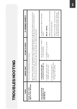
Page 18: ...p is connected to is working correctly 1 2 3 4 Connect the pump to the nearest working mains outlet Replace the plug fuse with the correct 5A fuse Try a different device in the mains outlet 1 2 3 IF P...

Page 19: ...NOTE Inflation can take up to 30 minutes The hoses are routed correctly not kinked and connected to the pump correctly The CPR valve is not trapped and is in the closed position 1 2 There are no leak...

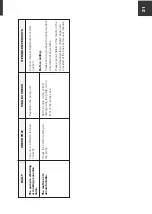
Page 20: ...equentially CHECK THAT FAULT STAGE 2 CHECK The system does not appear to be alternating Check that the static mode is not turned on Carefully mark one of the inflated cells with a pen Ensure that ther...

Page 21: ...s is uncomfortable Check the comfort setting on the pump Set the pump to the correct setting using the guide on the front of the pump case Contact Harvest Healthcare technical support Before calling P...

Page 22: ...3 PU204 PU205 Power Lead 5 Metres Inlet Power Lead Label Panel Tactile Timer and Motor Front Casing HPU2 Harvest 2 Pump only PU200 Connector PU206 Rear Casing PU207 PU208 Bed Hooks PCB UN012 Filter PU...

Page 23: ...uipment has been used for the purpose for which it was intended That the usage has been on a fair wear and tear basis This does not include user damage That Harvest Healthcare s cleaning disinfecting...

Page 24: ...www easycaresystems co uk...

Page 25: ...25 NOTES www easycaresystems co uk...

Page 26: ...26 NOTES www easycaresystems co uk...

Page 27: ...27 NOTES www easycaresystems co uk...

Page 28: ...28 Special Products and Service Contact Us Units 5 and 6 Lower Vicarage Road Southampton Hampshire SO19 7RJ T 02380 420678 E info easycaresystems co uk www easycaresystems co uk...

Reviews: