background image

RESULT

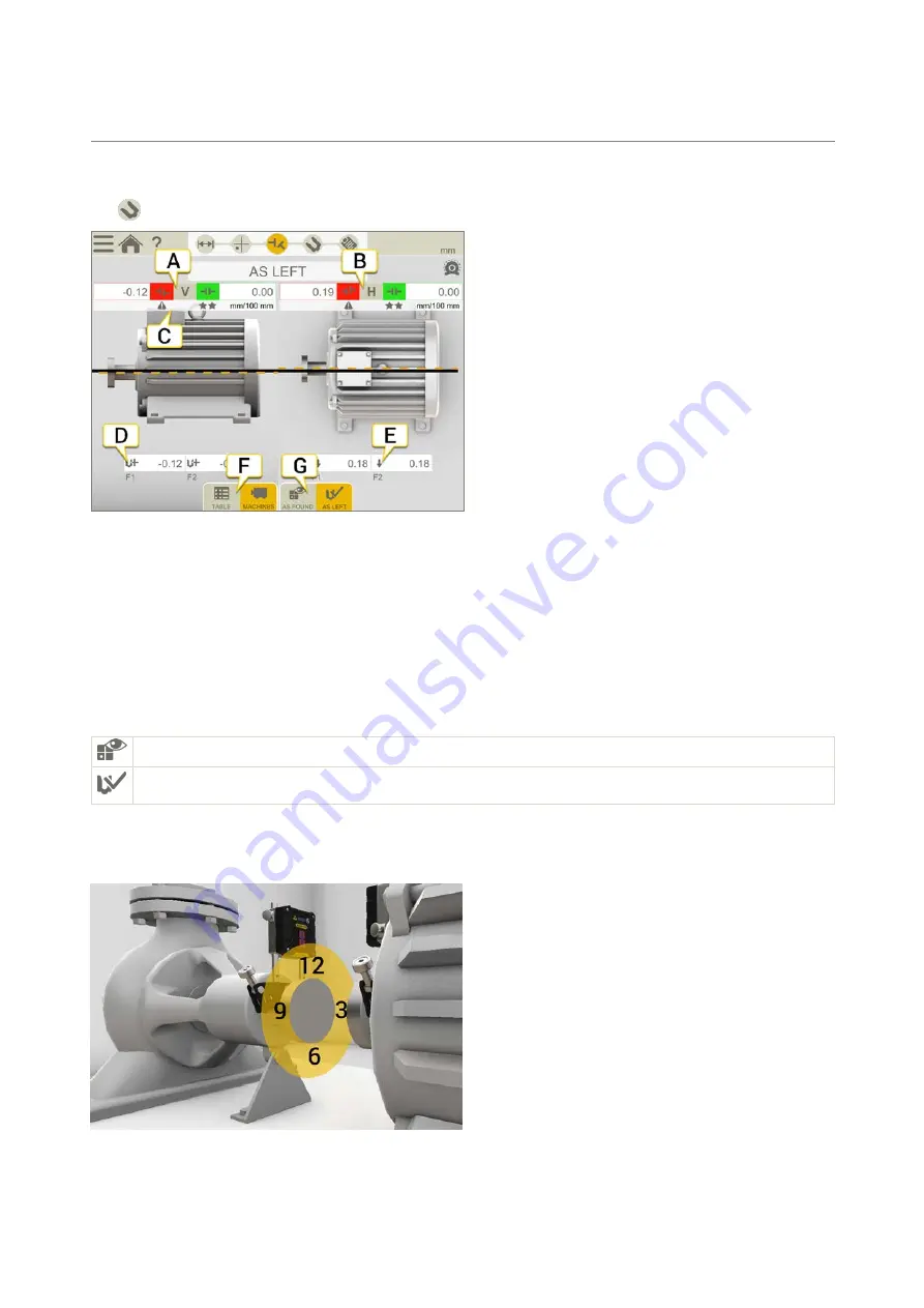
On the Result view, the offset, angle and feet values are clearly displayed. Both horizontal and vertical directions are 
shown. You can go back and forth between the views Measure, Result and Adjust. 

Tap 

 if you want to adjust the machine. After you have adjusted, it is possible to go back to the Result view. 

 A.  Vertical offset and angle values.

 B.  Horizontal offset and angle values.

 C.  Tolerance indicators. 

 D.  Vertical feet values.

 E.  Horizontal feet values.

 F.  Show Table or Machine view. See "Result table" on the next page

 G.  Show "As found" or "As left" values.

As found or As left

Toggle between showing:

As found is the latest measurement you made before going to the Result view.

As left is the latest adjusted result. Available if you have gone to the Adjust view (and shown live values) and 
returned to Result view.

How to read the values

When reading the values, face the stationary machine (S) from the movable machine (M). Then 9 o’clock is to the left, 
as in the measuring programs.

49

HORIZONTAL

Summary of Contents for XT11

Page 1: ...User Manual English 05 0835 EN Revision 2 0 User Manual last built 9 12 2017...

Page 2: ......

Page 3: ...er 13 Charge XT11 14 Camera 15 IR camera 16 Settings 16 Screenshot 18 Settings 19 Units 19 Language 19 User information 19 Time and date 20 Display 20 Wi Fi 21 System information 22 Update software 22...

Page 4: ...sing 9 12 3 43 Measure using Multipoint 45 Measure using Continuous sweep 47 Result 49 Result table 50 As found or As left 51 Quality assessment 52 Adjust 53 Live values for EasyTurn 53 Live values fo...

Page 5: ...ification 71 XT440 Shaft 73 A complete system contains 73 Customize your XT11 73 XT660 Shaft 75 A complete system contains 75 Customize your XT11 75 XT190 BTA 77 Laser transmitter 77 Detector 78 LEGAL...

Page 6: ...This page intentionally left blank to ensure new chapters start on right odd number pages...

Page 7: ...on Press to lock the touch function on the screen Prevents unintentional clicks for instance when moving between work positions D OK button E Tap the screen to open a program On the startscreen you w...

Page 8: ...s 100 No batteries the Display unit is run via the adapter Contact your Service center The battery is empty the Display unit will turn off in approx 5 seconds The cover is open usually after a battery...

Page 9: ...reate a editable copy of the finalized measurement See File manager on page 12 New or Continue session Tap the program icon to start a new measurement If you leave an ongoing measurement session the n...

Page 10: ...ze when you have finished your measurement See Report on page 55 1 Tap and 2 Enter a new name or leave the default name 3 Tap The file is finalized and no longer editable The measurement file is added...

Page 11: ...to create a simple template 1 Enter distances RPM and thermal compensation for example 2 Tap to finalize 3 Name the file The file is saved in the File manager 4 Tap to open the File manager 5 Tap to...

Page 12: ...ry stick Photos IR photos and screenshots Images are stored as png files The files are named with the date and time they were created Tap a file to open See Camera on page 15 See Screenshot on page 18...

Page 13: ...or instance moving heat sources or closing doors If the readings remain unstable increase the filter value more samples will become available to the statistical filter Select filter Tap to expand the...

Page 14: ...fully charge the battery takes approximately 3 hours It is possible to keep on using the equip ment while it is charging NOTE When finished working for the day charge the whole system Plug in the powe...

Page 15: ...Tap to take a photo The photo is saved in File manager as a png file It is named with current date and time If you have an ongoing meas urement the photo is added to the report Currently only one phot...

Page 16: ...aved in the File manager as a png file It is named with current date and time If you have an ongoing measurement the photo is added to the report If a new photo IR photo is taken the previous one will...

Page 17: ...e values 0 01 1 00 but we do not recommend value below 0 6 The value is normally set from a list of emissivity values for some common materials l 1 00 for a perfect blackbody l 0 01 for a perfect shin...

Page 18: ...possible to take screenshots of what is currently displayed on the XT11 screen 1 Press the button 2 Tap 3 The screen dump is saved in File manager as a png file It is named with current date and time...

Page 19: ...enu 2 Tap and select a language 3 Tap to close the Settings view Your new setting is saved User information The information you enter will be visible in the coming reports that is using the template D...

Page 20: ...gs are saved Display Adjust the brightness to make it easier to read in bright sunlight for example Remember however that a high contrast consume more battery power Default is set to 40 1 Tap on the s...

Page 21: ...i Fi A password is requested Wi Fi is turned off Turn off Wi Fi if you are in an environment where wifi is not permitted Remove the Wi Fi network from the list Connected to Wi Fi but no Internet conne...

Page 22: ...pen the Settings menu 2 Tap to show system information Update software 1 Go to our website to check for software updates 2 Download the updates to a USB 3 Insert the USB stick 4 Tap to open Settings a...

Page 23: ...ts To fully charge the battery takes approx 2 hours Operating time for XT40 and XT60 is up to 24 h It is possible to keep on using the equipment while it is charging NOTE When finished working for the...

Page 24: ...owing the angle value and battery information The info display becomes active when the measuring unit is started During start up the display shows the version of the equipment Start up takes approxima...

Page 25: ...g the XT40 See Measuring units XT40 on page 69 XT60 A On Off button B Connection for charging cable C Laser adjustment knob D Locking knob E Laser aperture Info display The measuring unit is equipped...

Page 26: ...approximately 3 seconds Malfunction Restart the unit if it does not help please contact your service center System failure Note the error code and contact your service center Turn off the unit do not...

Page 27: ...e is lit up as a warning It is still possible to register values when edge warning is active E Filter See Filter on page 13 F Autorecord See Autorecord on page 30 G Zero set or halve value Select meas...

Page 28: ...a note to the report See Report on page 55 See Camera on page 15 See Finalize on page 10 Available if you have opened a finalized measurement Opens a editable copy of the current measurement See New c...

Page 29: ...e 1 Tap on the tab to halve the displayed value Zero point of the target moves halfway towards the laser point 2 Tap on the tab to return to the absolute value Zero point of the target returns to the...

Page 30: ...b 2 Tap to start recording values 3 The recording will start and you can follow the progress on screen 4 Tap to stop the measurement A Indicates that values are being recorded B Tap to set duration an...

Page 31: ...nit The S unit s reading shall correspond to the movement within 1 1 mil 1 digit 0 01 mm 1 digit A Make sure that the distance is kept B Parallel lift to a known distance Shim exactly 1 mm NOTE The sh...

Page 32: ...32...

Page 33: ...ed out To see the report at its current state tap in the work flow The measurement is saved automatically through the entire workflow When you have finished the measurement tap and to finalize it l Pr...

Page 34: ...NOTE Make sure that the measuring units are charged Menu icons Tap to open the menu Mirror the machines Show Gap See Coupling diameter on page 36 Add a note to the report See Report on page 55 See Ca...

Page 35: ...ts Use the adjustment knob and or move the detectors on the rods 2 Turn the shafts 180 Make a mark on the rods or machine halfway between the laser line and center of both targets 3 Adjust the laser b...

Page 36: ...all distances and go directly to Measure view If you change a distance later on the result is recal culated l To calculate an offset and angle result you need to enter at least the distances between...

Page 37: ...to match the RPM you entered To change or inactivate the tol erance see Tolerance below Enter RPM Tolerance When you select a RPM value a matching tolerance is set automatically 1 On the coupling tap...

Page 38: ...Filter Filter If you have a low filter the detector filter is increased to filter 4 when you measure Softfoot If you increase the filter set ting while measuring Softfoot the new filter will be defau...

Page 39: ...nsation A Offline no compensation set The machines are aligned B Running the machine grows 5 mm and is no longer aligned Example with compensation In this example we assume a thermal growth of 5 mm in...

Page 40: ...Name the machine Use if you want to change the default names on the machines The name is visible in the report 1 Tap on the machine 2 Tap 3 Tap the text input field to change the name 40 HORIZONTAL...

Page 41: ...switch measuring method before you have registered a value 1 Tap on the tab to select the method EasyTurn 2 Adjust laser to the center of the targets If needed adjust the units on the rods then use l...

Page 42: ...ake a new measurement This makes it possible to check the repeatability of the measurement Measure using EasyTurn Measure using 9 12 3 Measure using Multipoint Measure using Continuous sweep Set Filte...

Page 43: ...select the method 9 12 3 2 Adjust laser to the center of the targets If needed adjust the units on the rods then use laser adjustments knobs 3 Turn shafts to 9 o clock 4 Tap to register the first pos...

Page 44: ...to check the repeatability of the measurement Measure using EasyTurn Measure using 9 12 3 Measure using Multipoint Measure using Continuous sweep Set Filter value See also See Result on page 49 See N...

Page 45: ...tion for a more accurate result 1 Tap on the tab to select the method Multipoint 2 Adjust laser to the center of the targets If needed adjust the units on the rods then use laser adjustments knobs 3 T...

Page 46: ...lues for each data point and sinusoidal curves fitted to the data points For an ideal coupling with no backlash perfect bearings etc the fitted lines will follow the measured points smoothly Devi atio...

Page 47: ...ect the method Continuous sweep 2 Adjust laser to the center of the targets If needed adjust the units on the rods then use laser adjustments knobs 3 Tap to start the measurement 4 Turn the shafts Tur...

Page 48: ...ta point and sinusoidal curves fitted to the data points For an ideal coupling with no backlash perfect bearings etc the fitted lines will follow the measured points smoothly Devi ations between data...

Page 49: ...ce indicators D Vertical feet values E Horizontal feet values F Show Table or Machine view See Result table on the next page G Show As found or As left values As found or As left Toggle between showin...

Page 50: ...To show the result as gap tap and Offset and angle values The offset and angle value indicate how well the machine is aligned at the coupling They appear in both horizontal and vertical direction The...

Page 51: ...cluded in the calculations but still visible The report will not be affected if you hide any measurements in the report it is always the latest measurements that are shown NOTE It is always the latest...

Page 52: ...alues from the units If the acquired accuracy is low it may depend on for example air turbulence or bearing clearance Temperature stability Measured temperature variation in the measuring units If the...

Page 53: ...port view A Vertical offset and angle values B Horizontal offset and angle values C Tolerance indicators D Add or remove shims E Arrow show how to adjust the horizontal val ues F Select which live val...

Page 54: ...measurement units are 1 Turn the shafts with detectors to a live position 2 Tap the corresponding live option see below 3 Tap before you leave the live position Live options Not live If you want to ch...

Page 55: ...can choose to save the report as a Pdf or an Excel file 1 Tap and 2 Enter a new name or leave the default name 3 Go to Report view 4 Tap and or The report is added to the File manager The Excel file i...

Page 56: ...aken the previous one will be overwritten Add user information The information you enter will be visible in the coming reports that is using the template Detailed 1 Tap on the startscreen to open the...

Page 57: ...pulleys can be aligned regardless of belt type You can com pensate for sheaves of varying widths For technical information See XT190 BTA on page 77 A Connector B Detector aperture C Battery Alkaline 1...

Page 58: ...A Offset B Angular C Both offset and angular misalignment 58 BELT...

Page 59: ...ave width and tolerance C Tap input field to enter distance D Tap to select detector E The Display unit automatically recognize where the units are placed F Set M unit to the left or right Mount the u...

Page 60: ...eave can be different on the two sheaves To calculate a possible offset the system requires both sheave face widths 1 Tap to open machine properties 2 Measure the distance from the belt to the axial f...

Page 61: ...Tolerance table Recommended maximum tolerances from manufacturers of belt transmissions is 0 25 0 50 Recommendations are always dependent on belt type Please consult the design manual of the specific...

Page 62: ...a separate tool See Measure without Display unit on page 64 A The Measure icon is active in the workflow B Vertical angular error To set tolerance See Tolerance on page 60 C Horizontal angular and off...

Page 63: ...or by repositioning one of the sheaves on its shaft l Correct vertical angular error by shimming the movable machine l Correct horizontal angular error by adjusting the movable machine with lateral j...

Page 64: ...splayed 3 Adjust machine see See Measure with Display unit on page 62 A Offset mm or inch B Horizontal angle C Vertical angle D Settings E On Off F Battery Settings Press to open the settings view Use...

Page 65: ...A Misaligned sheave B Aligned sheave the laser beam disappears in the slot of the target 65 BELT...

Page 66: ...l file The files are saved in the File manager D Tap to select a template See Report on page 55 NOTE The functions Share and Save as Pdf or Excel file are available after the measurement has been fina...

Page 67: ...ting time Up to 16 h continuously Connections USB A USB B Charger AV optional Communication Wireless technology Camera with diode lamp 13 Mp IR camera optional FLIR LEPTON Long Wave Infrared Help func...

Page 68: ...m 39 4 Charging voltage 15v Brackets etc Shaft brackets Type V bracket for chain width 18 mm 0 7 Shaft diameters 20 150 mm 0 8 6 0 Material anodize aluminum Rods Length 120 mm 60 mm 4 72 2 36 extendab...

Page 69: ...g temperature 10 50 C Storage temperature 20 50 C Relative humidity 10 95 OLED display 128x64 pixels Housing material Anodized aluminum PC ABS TPE Dimensions WxHxD 76x76 7x39 3 mm 3 0x3 0x1 5 Weight 2...

Page 70: ...A Laser beam on M unit B Laser beam on S unit Labels with safety precautions Label on the back of XT40 Label on the front of XT40 70 TECHNICAL DATA...

Page 71: ...Electronic inclinometer 0 1 resolution Environmental protection IP class 66 and 67 Operating temperature 10 50 C Storage temperature 20 50 C Relative humidity 10 95 OLED display 128x64 pixels Housing...

Page 72: ...gy Max 7 nJ Wavelength 630 680 nm Beam divergence 1 5 mrad x 200 mrad Pulse repetition frequency 75 120 kHz A Laser beam on M unit B Laser beam on S unit Labels with safety precautions Label on the ba...

Page 73: ...Hexagon wrench set 1 Charger 100 240 V AC 1 DC split cable for charging 1 DC to USB adapter for charging 1 Shoulder strap for display unit 1 Quick reference manual 1 Cleaning cloth for optics 1 USB m...

Page 74: ...Part No 12 0985 Camera removed from XT11 74 TECHNICAL DATA...

Page 75: ...in 900 mm 35 4 1 Measuring tape 3 m 9 8 1 Hexagon wrench set 1 Charger 100 240 V AC 1 DC split cable for charging 1 DC to USB adapter for charging 1 Shoulder strap for display unit 1 Quick reference m...

Page 76: ...Part No 12 0968 IR Camera added to XT11 Part No 12 0985 Camera removed from XT11 76 TECHNICAL DATA...

Page 77: ...odized aluminium Dimensions BxHxD 145x86x30 mm 5 7x3 4x1 2 Weight 270 g 9 52 oz NOTE If not using the system for a long period of time remove the battery from the laser transmitter Laser classificatio...

Page 78: ...ogy Battery type Li Ion Battery operation 5 hours continuously Housing material ABS plastics Anodized aluminium Dimensions BxHxD 95x95x36 mm 3 7x3 7x1 4 Weight 190 g 6 7 oz Detector battery Press to s...

Page 79: ...his device must accept any interference received including interference that may cause undesired operation Disposal of old electrical and electronic equipment Applicable throughout the European Union...

Page 80: ...new or serviceable used parts and is at least functionally equivalent to the original product Proof of purchase date should be confirmed and sent together with a copy of the original purchase document...

Page 81: ...irectly into the beam in particular for deliberate exposure The beam may cause strong temporary blindness especially under low ambient light conditions However the risk of injury for Class 2 laser pro...

Reviews: