background image

24


Eastwood Technical Assistance: 800.343.9353  >>  [email protected]

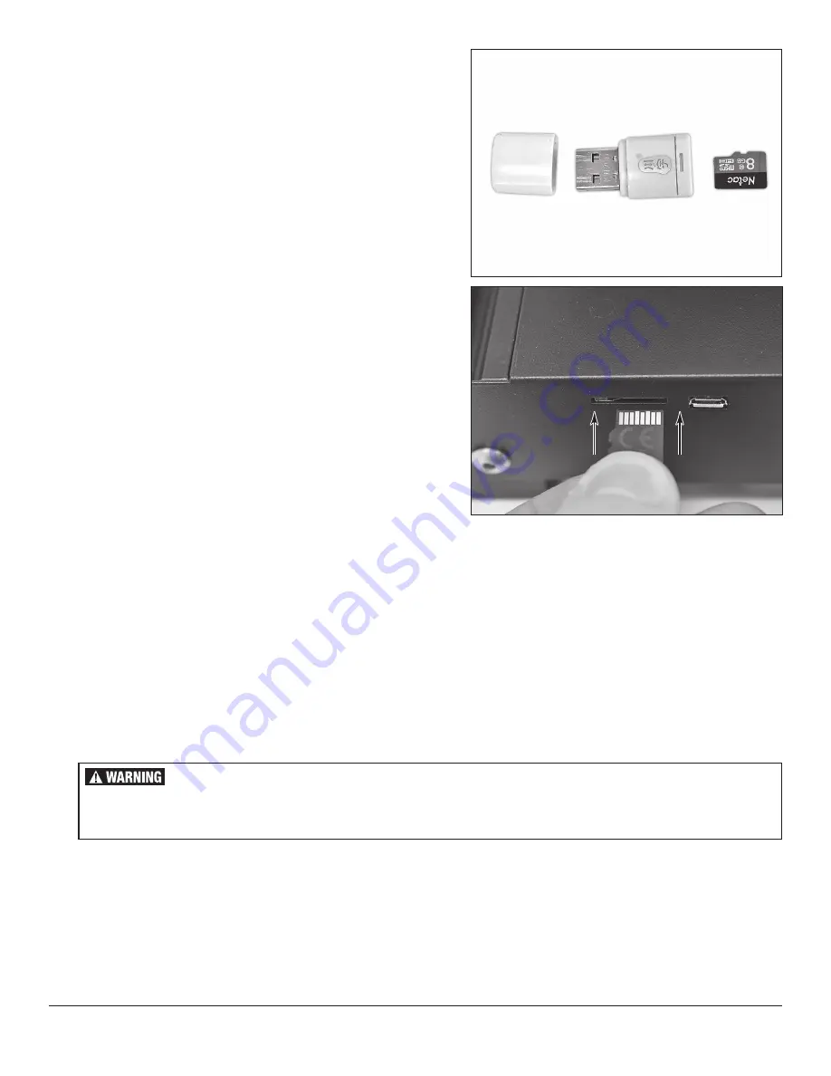
UTILIZING THE MICRO SD CARD AND USB ADAPTER

•  The included Micro SD to USB Adapter with 8GB Micro SD Card 

[HH]

 is used to 

transfer G-Code files from a computer to the 3D Printer 

(FIG 46)

.

•  The USB adapter with the Micro SD card installed can be plugged into a computer 

for file transfers.

•  Once files are transferred to the Micro SD card, it can be removed from the 

adapter and inserted into the Micro SD card port. Orient the contacts of the card 
upward and insert gently until a tactile click locks it in place 

(FIG 47)

. To remove, 

press until it unlocks then pull out.

•  The Micro SD card is preloaded with several files for Ultimaker Cura, G-Code test 

print files, and the start and end G-Code for slicers.

PRINTING A G-CODE FILE

•  With the G-code file saved to the Micro SD card, insert it into the machine.
•  From the main screen, select Print. Find the desired G-Code file by name and 

select it.

•  The printer will now heat up and then begin the print. The first layer is where 

the majority of 3D print failures will occur. Verify the filament adheres to the bed 
correctly by following the next steps. When the extrusion begins, get your eyes at 
level with the top surface of the bed and observe the height of the nozzle as the 
print begins.


°

  If the nozzle is too high there will be noticeable gap between the print surface  

  and the nozzle head, and the filament may curl up instead of sticking.  
  In this case, select 

Tune

 and adjust the 

Probe Z-Offset

 downward (which  

  will be a negative number) until the nozzle is very close to the print surface.  
  The filament should now be sticking.


°

  Next, bring your eyes up and observe the bead of extruded plastic being laid  

  down. If the nozzle is too close, the color and shape of the bead will be  
  shaped like a V because it has been compressed too much. Slowly adjust  
 the 

Probe Z-Offset

 upward until it appears flat and uniform.


°

  Optimal print height with good adhesion will produce a uniform bead of  

  filament that is stuck to the bed. Light side pressure from the putty knife  
  should not break adhesion.


°

  Do not be discouraged if it is difficult to get a good first layer. This is the most  

  difficult part of 3D printing and can take significant time and practice to  
  become proficient at, similar to MIG welding.

•  Progress percentage time elapsed, and approximate time left are shown on the 

screen. After the print has completed it will show the time elapsed and ask for 
confirmation that the print has been completed before continuing.

BURN HAZARD! 

  Contact with the Eastwood Genesis FDM 3D Printer Nozzle, Bed or printed parts can cause serious burns.  

Allow sufficient time for cooling before touching finished printed parts.  
Wear protective heat-resistant gloves when using this equipment.

FIG. 46

FIG. 46

FIG. 47

FIG. 47

REMOVING PARTS FROM THE BUILD PLATE

•  To remove parts from the build plate, care must be taken to not damage the part or the build surface.
•  Allow, at minimum, 5 - 10 minutes for the part to cool. Parts with larger first layer surface area need longer because they retain more heat. Removing a 

part with the build plate at high temperatures can easily result in bottom damage and distortion of the print because it will remain somewhat soft until 
temperatures have dropped to near ambient. The closer a part is to ambient temperatures the easier it will separate.

•  Utilize the included putty knife to work under the part and, if possible, lightly pry on it with your hand to assist. Parts should separate relatively easy.

Protective 

Cap

Micro SD to 

USB Adapter

Micro SD 

Card

Summary of Contents for 60381

Page 1: ...GENESIS FDM 3D PRINTER ASSEMBLY AND OPERATING INSTRUCTIONS Item 60381...

Page 2: ...Gal 1 9 HP Compressor Eastwood XL View Welding Helmet Eastwood Lg View Welding Helmet Eastwood Auto Darkening Helmet Concours 2 HVLP Paint Gun Items not covered under this warranty Consumables unless...

Page 3: ...IFICATIONS 3 INCLUDES 4 SAFETY INFORMATION 6 GENESIS FDM 3D PRINTER COMPONENT IDENTIFICATION 7 3D PRINTING GLOSSARY OF TERMS 8 GENESIS FDM 3D PRINTER SETUP ASSEMBLY 9 PLACEMENT 15 POWERING ON 15 OPERA...

Page 4: ...R 1 Extruder Manual Drive Wheel S 1 Nozzle Clearing Rod T 1 X Axis Belt Tensioner U 1 X Axis Belt V 1 Spare Nozzle W 2 PTFE Tube Fitting X 2 Tube Fitting Lock Clip Y 5 M5x45 Hex Cap Screw w retained L...

Page 5: ...To order parts and supplies 800 343 9353 eastwood com 5 A FIG A FIG A FIG B FIG B B C D E F G H J K M N Q V Z AA BB CC DD EE FF GG HH JJ KK MM NN PP QQ RR P R S T U W X Y...

Page 6: ...ved respiratory protection while using this Eastwood Genesis FDM 3D Printer EYE INJURY HAZARD Hot plastic may be ejected printing process Eye protection should be worn at all times when operating this...

Page 7: ...r b Extruder Drive Assembly c Hot End Assembly d Nozzle e X Axis Belt Tension Adjuster f Print Bed g Print Bed Leveling Adjustment Wheels h Y Axis Belt Tension Adjuster j Micro SD Card Port k Micro US...

Page 8: ...ware and the one that Eastwood recommends Extruder The component group that forces the filament through the feed tube and extrudes it out the hot nozzle is called the extruder Extruders usually consis...

Page 9: ...nd four M5x45 Hex Cap Screws Z Flip the Base Assembly up on its side for easy access to the bottom FIG 4a Insert the screws through the bottom and thread them into the aluminum extrusions of the Z Axi...

Page 10: ...the X Axis Belt V in the channel and loop it around the stepper motor drive gear to the bottom side Pull it halfway down the bottom side FIG 8 Roll the hot end assembly onto the X Axis Beam with the h...

Page 11: ...ything in place FIG 14 Now the thread another M4x16 Button Cap Screw BB from the rear into the remaining hole through the plate into the aluminum extrusion While tightening make the edge of the plate...

Page 12: ...Axis gantry up to the top of its range FIG 18 and tighten the four screws for the Z Axis Upright Brace The X Axis gantry should move up and down perfectly smooth now Install the Z Axis Stepper Motor A...

Page 13: ...motor mounting screws again and utilize thin shims to achieve perfect alignment For reference the pictured unit required an approximately 0 035 thick shim FIG 21 Once aligned snug the collar so the ro...

Page 14: ...plug in the 6 pin connector for the Z Axis stepper motor from the base assembly tagged Z Unmount the Control Panel P from the mount by sliding it upward FIG 26 and use the preinstalled hardware to ins...

Page 15: ...the regular living space such as a garage or shop The printer may suffer performance problems in excessive ambient temperatures Room temperature is ideal however if required printing can be done in 5...

Page 16: ...gs a beginner may adjust are nozzle temperature bed temperature and preheat profile settings MAIN SCREEN MENUS FIG 31 PRINT FIG 32 The print option allows immediate access to the storage device for se...

Page 17: ...reater than 180 C Disable Steppers Turns off all stepper motors Select this before trying to manually move any stepper motors to avoid possible damage Auto Home Auto zeros all three axes by contacting...

Page 18: ...Settings Control and save all parameters for this preheat profile Nozzle Temp Bed Temp Fan Speed Store Settings Profile 2 Settings Control and save all parameters for this preheat profile Nozzle Temp...

Page 19: ...Fan Speed Control the part cooling fan speed relative adjustment 0 255 Probe Z Offset The Z Offset is a very useful option for the start of the first layer It allows you to adjust the Z Axis height a...

Page 20: ...d print bed will result in a poor first layer Before using the printer the print bed must be levelled Once the levelling has been complete it does not need to be changed unless a degradation in qualit...

Page 21: ...NOTE It is a good practice when 3D printing to never leave the nozzle fully heated with the filament stationary for long periods of time This can lead to heat creep and create filament jams UNLOADING...

Page 22: ...d unless familiar with G code programming FIG 43 FIG 43 FIG 44 FIG 44 FIG 45 FIG 45 Start G Code Eastwood Genesis FDM 3D Printer Start G Code G92 E0 Zero extruder G28 Auto home G1 Z2 F3000 Move Z up 2...

Page 23: ...depends on the filament at hand and sometimes bed conditions Bed temperature allows for the filaments to be softer and stick to the build plate easier with little to no lifting or shifting Guidelines...

Page 24: ...truded plastic being laid down If the nozzle is too close the color and shape of the bead will be shaped like a V because it has been compressed too much Slowly adjust the Probe Z Offset upward until...

Page 25: ...you loaded PLA Eastwood Logo gcode or PETG Eastwood Logo gcode The printer will automatically load all necessary settings from the G Code and begin printing when the build plate and nozzle have warme...

Page 26: ...1 75 0 05mm dia tolerance or better Speed too high We recommend to not exceed 60mm sec for standard filaments Filament spool not feeding all Verify filament spool is feeding smoothly and not knotted o...

Page 27: ...To order parts and supplies 800 343 9353 eastwood com 27 NOTES...

Page 28: ...Shoemaker Road Pottstown PA 19464 USA 800 343 9353 eastwood com ADDITIONAL ITEMS CONSUMABLE ITEMS 60395 5pc 0 4mm Nozzle Set 60398 PTFE Tube Kit 1m Length FILAMENTS 59984 Eastwood PLA Filament 1 75mm...

Reviews: