background image

20


Eastwood Technical Assistance: 800.343.9353  >>  [email protected]

PREPARING TO PRINT

SETTING Z-AXIS LIMIT SWITCH HEIGHT

It may be necessary to fine-tune the height of the Z-Axis Limit Switch to get the nozzle 
to an appropriate height above the bed before levelling it.

•  Start by adjusting the bed levelling screws down 

(FIG 37)

 in an even fashion. 

Note that the minimum bed height is limited by the Y-Axis stepper motor. Allow 
enough clearance for the bed to be pushed completely rearward without scraping 
anything on the stepper motor. Having the springs under greater tension makes 
for a more stable bed.

•  Power on the printer and select 

Prepare > Auto home

. This will return the 

printer to the zero position.

•  If the nozzle collides with the bed the limit switch must be adjusted up to provide 

the nozzle sufficient clearance to fit a sheet of paper under it. Re-perform Auto 
home to verify good clearance 

(FIG 37)

.

•  If the nozzle is significantly higher than the print surface, adjust leveling screws. 

If the travel limit of the screws will be exceeded, adjust the limit switch down and 
re-level. Re-perform Auto home to verify good clearance.

•  Once the Z-Axis Limit Switch is adequately adjusted make sure the fasteners are 

tight enough that it will not shift.

LEVELING THE PRINT BED

An unleveled print bed will result in a poor first layer. Before using the printer, the  
print bed must be levelled. Once the levelling has been complete, it does not need to  
be changed unless a degradation in quality of the first layer is noticed, or something  
has changed the level: e.g., changing a nozzle, removing the hot end, or moving the  
print bed.

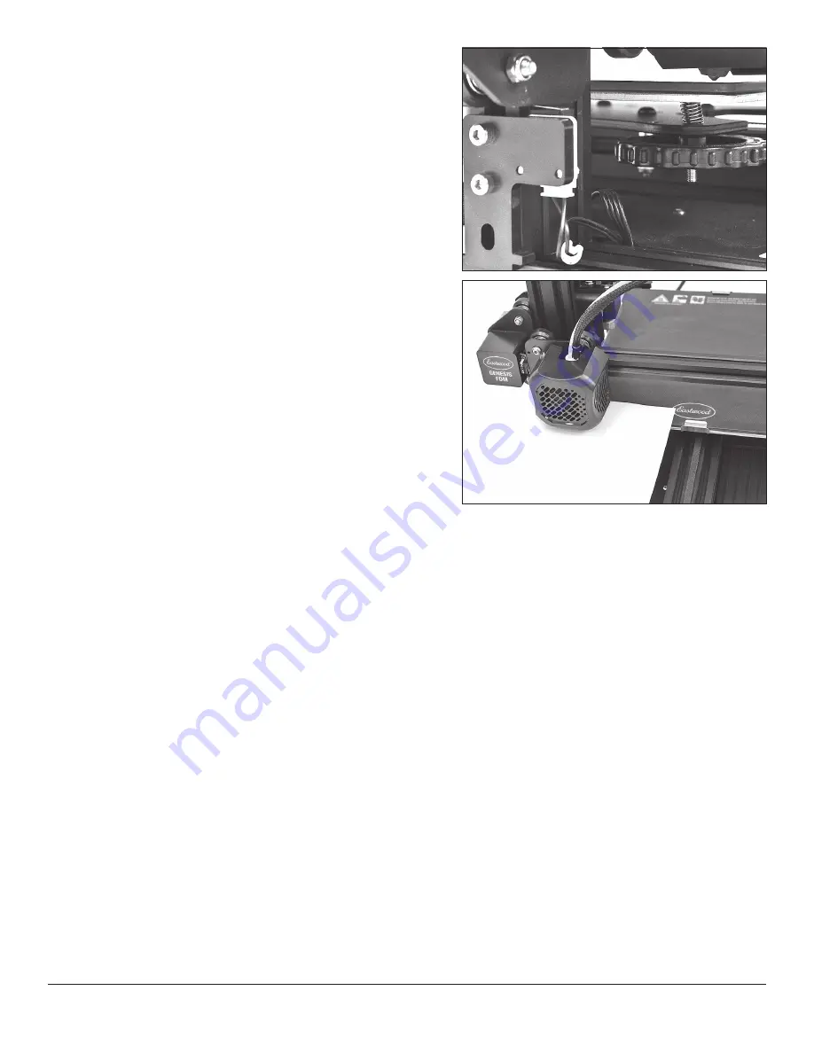
•  One of the simplest methods to get a good bed level is utilizing a clean sheet 

of printer paper as a feeler gauge. Auto home the printer and slide the piece of 
paper underneath the nozzle.

•  Slide the piece of paper back and forth, feeling for resistance, as that corner of 

the bed is adjusted slowly upward with the leveling wheel. Once the paper starts 
to contact the nozzle, stop adjusting 

(FIG 38)

.

•  Next, in 

Prepare > Move

, adjust the Z-Axis up approximately 1mm so that it 

will not collide with the bed clip or surface as it traverses. Adjust the X-Axis to 
220mm (maximum).

•  Slide the piece of paper back under the nozzle and readjust the Z-Axis back to 

0mm. Now repeat the same process of adjustment at this corner.

•  Once finished, adjust the Z-Axis up at least 1mm and move the Y-Axis to 220mm 

as well. Lower Z-Axis and repeat levelling process. Next, move to the final corner 
0mm X-Axis, 220mm Y-Axis and repeat.

•  Repeat the process rotating around and levelling every corner until the resistance 

on the paper at each corner feels equal. This can take several rotations as fine-
tuning is done.

•  The bed is now level and ready to print.

FIG. 37

FIG. 37

FIG. 38

FIG. 38

Summary of Contents for 60381

Page 1: ...GENESIS FDM 3D PRINTER ASSEMBLY AND OPERATING INSTRUCTIONS Item 60381...

Page 2: ...Gal 1 9 HP Compressor Eastwood XL View Welding Helmet Eastwood Lg View Welding Helmet Eastwood Auto Darkening Helmet Concours 2 HVLP Paint Gun Items not covered under this warranty Consumables unless...

Page 3: ...IFICATIONS 3 INCLUDES 4 SAFETY INFORMATION 6 GENESIS FDM 3D PRINTER COMPONENT IDENTIFICATION 7 3D PRINTING GLOSSARY OF TERMS 8 GENESIS FDM 3D PRINTER SETUP ASSEMBLY 9 PLACEMENT 15 POWERING ON 15 OPERA...

Page 4: ...R 1 Extruder Manual Drive Wheel S 1 Nozzle Clearing Rod T 1 X Axis Belt Tensioner U 1 X Axis Belt V 1 Spare Nozzle W 2 PTFE Tube Fitting X 2 Tube Fitting Lock Clip Y 5 M5x45 Hex Cap Screw w retained L...

Page 5: ...To order parts and supplies 800 343 9353 eastwood com 5 A FIG A FIG A FIG B FIG B B C D E F G H J K M N Q V Z AA BB CC DD EE FF GG HH JJ KK MM NN PP QQ RR P R S T U W X Y...

Page 6: ...ved respiratory protection while using this Eastwood Genesis FDM 3D Printer EYE INJURY HAZARD Hot plastic may be ejected printing process Eye protection should be worn at all times when operating this...

Page 7: ...r b Extruder Drive Assembly c Hot End Assembly d Nozzle e X Axis Belt Tension Adjuster f Print Bed g Print Bed Leveling Adjustment Wheels h Y Axis Belt Tension Adjuster j Micro SD Card Port k Micro US...

Page 8: ...ware and the one that Eastwood recommends Extruder The component group that forces the filament through the feed tube and extrudes it out the hot nozzle is called the extruder Extruders usually consis...

Page 9: ...nd four M5x45 Hex Cap Screws Z Flip the Base Assembly up on its side for easy access to the bottom FIG 4a Insert the screws through the bottom and thread them into the aluminum extrusions of the Z Axi...

Page 10: ...the X Axis Belt V in the channel and loop it around the stepper motor drive gear to the bottom side Pull it halfway down the bottom side FIG 8 Roll the hot end assembly onto the X Axis Beam with the h...

Page 11: ...ything in place FIG 14 Now the thread another M4x16 Button Cap Screw BB from the rear into the remaining hole through the plate into the aluminum extrusion While tightening make the edge of the plate...

Page 12: ...Axis gantry up to the top of its range FIG 18 and tighten the four screws for the Z Axis Upright Brace The X Axis gantry should move up and down perfectly smooth now Install the Z Axis Stepper Motor A...

Page 13: ...motor mounting screws again and utilize thin shims to achieve perfect alignment For reference the pictured unit required an approximately 0 035 thick shim FIG 21 Once aligned snug the collar so the ro...

Page 14: ...plug in the 6 pin connector for the Z Axis stepper motor from the base assembly tagged Z Unmount the Control Panel P from the mount by sliding it upward FIG 26 and use the preinstalled hardware to ins...

Page 15: ...the regular living space such as a garage or shop The printer may suffer performance problems in excessive ambient temperatures Room temperature is ideal however if required printing can be done in 5...

Page 16: ...gs a beginner may adjust are nozzle temperature bed temperature and preheat profile settings MAIN SCREEN MENUS FIG 31 PRINT FIG 32 The print option allows immediate access to the storage device for se...

Page 17: ...reater than 180 C Disable Steppers Turns off all stepper motors Select this before trying to manually move any stepper motors to avoid possible damage Auto Home Auto zeros all three axes by contacting...

Page 18: ...Settings Control and save all parameters for this preheat profile Nozzle Temp Bed Temp Fan Speed Store Settings Profile 2 Settings Control and save all parameters for this preheat profile Nozzle Temp...

Page 19: ...Fan Speed Control the part cooling fan speed relative adjustment 0 255 Probe Z Offset The Z Offset is a very useful option for the start of the first layer It allows you to adjust the Z Axis height a...

Page 20: ...d print bed will result in a poor first layer Before using the printer the print bed must be levelled Once the levelling has been complete it does not need to be changed unless a degradation in qualit...

Page 21: ...NOTE It is a good practice when 3D printing to never leave the nozzle fully heated with the filament stationary for long periods of time This can lead to heat creep and create filament jams UNLOADING...

Page 22: ...d unless familiar with G code programming FIG 43 FIG 43 FIG 44 FIG 44 FIG 45 FIG 45 Start G Code Eastwood Genesis FDM 3D Printer Start G Code G92 E0 Zero extruder G28 Auto home G1 Z2 F3000 Move Z up 2...

Page 23: ...depends on the filament at hand and sometimes bed conditions Bed temperature allows for the filaments to be softer and stick to the build plate easier with little to no lifting or shifting Guidelines...

Page 24: ...truded plastic being laid down If the nozzle is too close the color and shape of the bead will be shaped like a V because it has been compressed too much Slowly adjust the Probe Z Offset upward until...

Page 25: ...you loaded PLA Eastwood Logo gcode or PETG Eastwood Logo gcode The printer will automatically load all necessary settings from the G Code and begin printing when the build plate and nozzle have warme...

Page 26: ...1 75 0 05mm dia tolerance or better Speed too high We recommend to not exceed 60mm sec for standard filaments Filament spool not feeding all Verify filament spool is feeding smoothly and not knotted o...

Page 27: ...To order parts and supplies 800 343 9353 eastwood com 27 NOTES...

Page 28: ...Shoemaker Road Pottstown PA 19464 USA 800 343 9353 eastwood com ADDITIONAL ITEMS CONSUMABLE ITEMS 60395 5pc 0 4mm Nozzle Set 60398 PTFE Tube Kit 1m Length FILAMENTS 59984 Eastwood PLA Filament 1 75mm...

Reviews: