21
®
X Offset: Spindle offsets relate to a common point, usually
referring to the laser pointer. These offsets are necessary
due to the spindles’ physical distance from each other. X
Offset is a measure of the selected tool’s distance from the
laser point in the X-axis.
Y Offset: A measure of the selected tool’s distance from
the laser point in the Y-axis.
Z Offset: The Z Offset specifies how far the selected tool will
move from the Z sensor during the Table Zero or Panel Zero
functions. Z Offset is used to center a tool’s rotational direc-
tion.
Down Time: Specifies a wait time after the selected tool
drops to the cutting table. The machine will pause this time
before moving.
Up Time: Wait time after the tool has lifted for the machine
to move.
Down Bit: Command bit to drop the tool.
Enable: Turns the selected tool on or off. You may wish to
use this feature if, for example, you want to make only pen
markings on material.
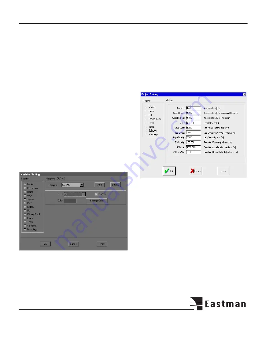
The Machine Setting Mappings screen.
The Mappings screen is used to map layers in cut files to
appropriate tools. For example, in a CMD file, lines to be
drawn are labeled PENME. As shown above, PENME has
been mapped to the PENN. CUTME, again a CMD format
layer name, indicates lines which are to be cut. Therefore,
CUTME should be mapped to a cutting tool such as R1 (1"
round knife) or DRG1 (drag knife).
Different file formats have different layer names, all of which
need to be mapped to tools, so users who work with several
file formats may require a lengthy mapping menu.
The On/Off button may be used to ignore mapped layers if
desired. Each layer in the Mapping menu may be turned on
or off when selected. Note that only a layer may be turned
off. If a tool is mapped to two different layers, turning off one
layer will not prevent the tool from being used on the other
one.
The Options menu Project Setting screen.
This screen is accessed only after opening a project in the
Project drop-down menu. Project Setting allows you to
override machine setting parameters in order to handle, for
example, the different requirements of different materials.
Certain materials may need more overcut, air pressure, etc.
to achieve efficient, accurate cutting. Changes made to these
machine settings will be applied only to the selected project.
Each project, therefore, may have its own unique param-
eters.
The project feature may be useful in other ways as well. You
can create a project to group together files, which are fre-
quently used together, or for any reason you wish. When a
project is created, its initial parameters are copied directly
from Machine Settings, so you don’t have to go through
and enter all the settings.
Summary of Contents for ETS-SLS-2
Page 1: ......
Page 24: ...24 Notes ...
Page 25: ...25 Notes ...
Page 26: ...26 Notes ...
Page 28: ......


