


18 Installation and Set Up
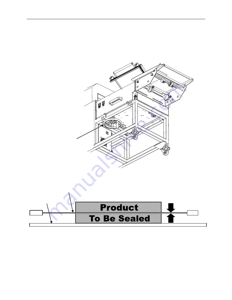
Seal Head Height Adjustment
To adjust the vertical height of the sealing band, use the height adjustment wheel
located under the sealing assembly. Turn the wheel to move the seal band position up
or down.
Position the sealing band as near as possible to the center of the product to be sealed.
Seal Head Height
Adjustment Wheel
Sealing Band
Take Away
Conveyor
Center the sealing
band on the side of the
product to be sealed
Summary of Contents for L-Bar Sealer Tunnel Combo Unit Value Series
Page 1: ...VS1620 L Bar Sealer Tunnel Combo Unit Value Series User Guide ...
Page 2: ......
Page 4: ......
Page 7: ......
Page 36: ...36 Parts List ElectricalSchematic Sheet1of2 ...
Page 37: ...Parts List 37 ElectricalSchematic Sheet2of2 ...
Page 38: ...38 Parts List VS1620 L Sealer Tunnel Combo Unit MainAssembly ...
Page 48: ...48 Parts List HeatTunnelOuterJacket VS1620DC ...
Page 50: ...50 Parts List L SealerAndFrame VS1620E ...
Page 54: ...54 Parts List L SealerTakeawayConveyor LTS504B P ...
Page 61: ......
Page 62: ......


