background image

ASSEMBLY  


UNPACKING 

This product requires assembly. 

Carefully remove the product and any accessories from the box.  
Make sure that all items listed in the packing list are included. 

Inspect the product carefully to make sure no breakage or   
damage occurred during shipping. 

Do not discard the packing material until you have carefully 
inspected and satisfactorily operated the product . 

If any parts are damaged or missing, please call our customer 
service help line at 1-800-313-5111 for assistance. 

PACKING LIST  

- Blower / Vac 
- Blower Tube 
- Vac Tube  
- Collection Bag 
- Operator’s manual  
 

WARNING: 

If any parts are damaged or missing do not op-

erate this product until the parts are replaced. Failure to heed 
this warning could result in serious personal injury. 

WARNING: 

Do not attempt to modify this product or create 

accessories not recommended for use with this product .Any 
such alteration or modification is misuse and could result in a 
hazardous condition leading to possible serious personal injury. 

WARNING: 

Do not connect to power supply until assembly 

is complete. Failure to comply could result in accidental starting 
and possible serious personal injury. 

CORD RETAINER 

A cord retainer is incorporated into 
the rear of the power head. 
If using more than one extension 
cord,  first tie the two cords in a 
knot as shown. 
Then, double the extension cord 
several inches from the end and 
hook the loop formed by doubling 
the cord over the retainer post as 
shown. 


ASSEMBLING THE UNIT AS A BLOWER 

Connect the two blower tubes together. 

Fit the larger diameter end of blower tubes onto the air outlet of 
the motor housing. 

Ensure the inlet cover is securely fastened over the air inlet 
before using blower function. 

ASSEMBLING THE UNIT AS A VACUUM 

Push the lower vacuum tube firmly into the upper tube until they are 
locked firmly together.  Once the vacuum tubes are connected, they 
should never be disassembled again. 

 
Remove the inlet cover from the bottom of the motor housing by de-
pressing the lock button and pulling the cover downward. 

Attach the vacuum tube assembly to the motor housing by positioning 
the assembly as indicated by arrow, then pivot about this point until 
the locking/release catch is fully engaged. 

Attach the push-on collection bag connector to the outlet tube of the 
housing. Push the fitting of the collection bag directly onto the outlet 
until it “clicks” into position. 


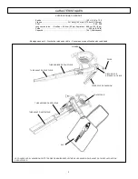
INLET COVER


BLOWER  TUBES


CORD RETAINER


VACUUM  TUBES


COLLECTION BAG


Summary of Contents for BVM22012

Page 1: ...ease of operation and operator safety Properly cared for it will give you years of rugged trouble free performance WARNING To reduce the risk of injury the user must read and understand the operator...

Page 2: ...ornia to cause cancer and birth defects or other reproductive harm Some examples of these chemicals are chemicals in fertilizers compounds in insecticides herbicides and pesticides arsenic and chromiu...

Page 3: ...cuum Weight 9 26 Ib Capacity 2 Bushels INLET COVER MUST BE SECURELY ATTACHED TO AIR INLET PRIOR TO USING BLOWER FUNCTION CORD RETAINER FRONT BLOWER TUBE REAR BLOWER TUBE HANDLE No Tool Assembly Cord R...

Page 4: ...e serious personal injury CORD RETAINER A cord retainer is incorporated into the rear of the power head If using more than one extension cord first tie the two cords in a knot as shown Then double the...

Page 5: ...of the housing Push the fitting of the collection bag directly onto the outlet until it clicks into position Position the tube slightly above the debris leaves Switch the tool on then using a sweepin...

Page 6: ...ic IMPORTANT To assure product SAFETY and RELIABILITY repairs maintenance and adjustment should be performed by a qualified individual using only identical replacement parts Possible Cause Extension c...

Page 7: ...___________________________________________________________________ ____________________________________________________________________ _______________________________________________________________...

Page 8: ...adjustments explained in the operator s manual Damage or liability caused by shipping improper handling im proper installation incorrect voltage or improper wiring improper maintenance improper modif...

Page 9: ...para el operario Si se la trata con cuidado le otorgar a os de ptimo rendimiento y resistencia ADVERTENCIA Para reducir el riesgo de sufrir alguna lesi n el usuario debe leer y comprender el manual de...

Page 10: ...nacimiento u otros efectos nocivos para el aparato reproductor ADVERTENCIA Parte del polvo y los desechos generados por el uso de esta herramienta contienen qu micos reconocidos por el Estado de Cali...

Page 11: ...ros 2 Bushels LA TAPA DE LA BOCA DE ENTRADA DE AIRE DEBE ESTAR BIEN COLOCADA SOBRE LA ENTRADA DE AIRE ANTES DE UTILIZAR LA UNIDAD EN MODO DE SOPLADO RETENEDOR DE CABLE TUBO FRONTAL DE SOPLADO TUBO POS...

Page 12: ...ad RETENEDOR DE CABLE La parte posterior del cabezal de potencia incluye un retenedor de cable Si se utiliza m s de un cable de extensi n primero ate los dos cables con un nudo como se muestra A conti...

Page 13: ...a de la bolsa de recolecci n directamente sobre la salida hasta que haga clic al trabarse en su posici n Ubique el tubo ligeramente por encima de los desechos y hojas Encienda la herramienta y luego c...

Page 14: ...aciones el mantenimiento y los ajustes deben estar a cargo de una persona calificada y se deben utilizar repuestos id nticos nicamente Posible causa El cable de extensi n no est conectado al enchufe E...

Page 15: ...___________________________________________________________________ ____________________________________________________________________ _______________________________________________________________...

Page 16: ...ustes normales que se explican en el manual del operario Da os ni inconvenientes causados por env o manipulaci n inadecuada instalaci n incorrecta voltaje o cableado incorrecto mantenimiento deficient...

Page 17: ...Correctement entretenu il vous procurera des ann es de service intensif et sans souci AVERTISSEMENT Afin d viter de se blesser l utilisateur doit lire et comprendre le manuel de l utilisateur avant d...

Page 18: ...cr s par l utilisation de cet outil sont susceptibles de contenir des produits chimiques qui sont canc rig nes et l origine de malformations cong nitales ou d autres troubles de l appareil reproducteu...

Page 19: ...70 4 l 2 boisseaux LE COUVERCLE DE L ADMISSION DOIT TRE FIX DE MANI RE S CURITAIRE L ADMISSION D AIR AVANT D UTILISER LA FONCTION DE SOUFFLEUR DISPOSITIF DE RETENUE DU C BLE TUBE AVANT DE SOUFFLEUR TU...

Page 20: ...DU C BLE Un dispositif de retenue du c ble est incorpor sur l arri re du moteur En cas d utilisation de plusieurs rallonges nouez d abord les deux c bles comme indiqu Doublez ensuite la rallonge sur p...

Page 21: ...arter Enfoncez le raccord du sac de collecte directement dans la sortie jusqu ce qu il s enclenche Positionnez le tube l g rement au dessus des d bris feuilles Mettez l outil en marche et l aide d un...

Page 22: ...plastique IMPORTANT Pour garantir la S CURIT et la FIABILIT du produit les r parations la maintenance et le r glage doivent tre effectu s par une personne qualifi e qui utilise toujours des pi ces de...

Page 23: ...___________________________________________________________________ ____________________________________________________________________ _______________________________________________________________...

Page 24: ...esponsabilit s provoqu s par le transport une mauvaise manipulation une mauvaise installation une tension ou un c blage incorrect une mauvaise maintenance une modification incorrecte ou l utilisation...

Reviews: