ACM-410D-IM (11/12)
Page 11
4. Install two-pole terminal strip inside electrical box and fasten into existing hole with screw
provided.
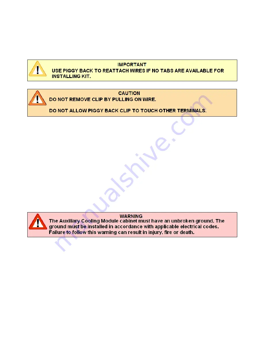
5. Attach pink wire with piggyback connector onto “T2” (for single phase) or “T3” (for three
phase) on the compressor contractor and the other connector to the center terminal of the
bottom fuse holder.
6. Attach the gray wire with the piggy back connector onto “L1” on the compressor contactor,
and the other connector to the center terminal of the top fuse holder.
7. Attach the pink wire with connector to the collar connection of the bottom fuse holder, and
tighten the terminal screw of the terminal block onto the stripped end of the pink wire.
8. Attach the gray wire with connector to the collar of the top fuse holder, and tighten the other
terminal screw of the terminal block onto the stripped end of the gray wire.
9. Run high voltage wiring from the two-pole terminal strip in the electrical box out of the
grommeted end hole of the electrical box and through the conduit connection of the
compressor cabinet, to the Disconnect shown in Figure 6, and from the Disconnect to the
Auxiliary Cooling Module, using flexible conduit.
10. After running the power wiring in flexible conduit to the Auxiliary Cooling Module, remove
the Auxiliary Cooling Module electric box cover.
11. The Auxiliary Cooling Module control box contains a Ranco pressure control that has been
factory set to energize the Auxiliary Cooling Module at a predetermined compressor
discharge pressure.
DO NOT ATTEMPT TO ADJUST THIS CONTROL!
Figure 6 illustrates the electrical connections that are to be made at the ACM electric box
with the two high voltage leads from the compressor unit.


