30
Earthcore Industries
BVETTO B-Vent Gas Fireplace
08/2017
ISOKERN Gas Log Set - Burner Installation
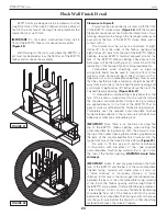
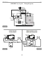
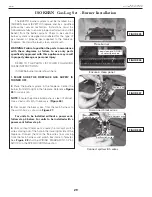
5. Units with Power vent:
Locate the two spill switch
and two power vent wires coming out of the hole in
the lower right side of the fireplace. Connect them to
the free wires now coming from the main harness and
switch box (male to female). See
Figure 39
,
Figure 40
,
and the WIRING DIAGRAM TO SPILL SWITCH AND
POWER VENT in the SPECIFICATIONS section.
6.
At this stage the burner system batteries are to be
installed. Reference the INSTALLING/REPLACING
BATTERIES section for details.
7.
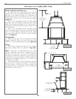
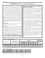
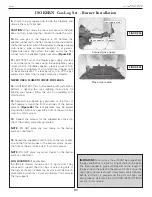
Place the switch box on its side, at the rear left corner
of the fireplace. It should rest with its bottom as near as
possible and facing the fireplace wall. It must not be
placed directly next to the burner pan area to avoid
damage to the batteries. See
Figure 41
&
Figure 42
.
IMPORTANT:
Ensure that the box wire remains away
from the burner system and its flame during operation.
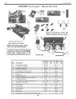
8.
Place the decorative heat shield over the switch box as
shown in
Figure 43
.
Place heat shield
Must rest on fl oor and at rear corner
Proper box placement
Place switch box:
• Rear left corner, on side,
• exposed side against fi replace wall
DO NOT
place box
in this area
Place switch box
Connect spill switch and power vent wires
Connect power vent to switch box wire
Spill switch wire
Main harness wire
Spill switch wire
Switch box wire
Power vent wire
Power vent wire
Place switch box
FIGURE 39
FIGURE 40
FIGURE 41
FIGURE 42
FIGURE 43


