Geneva Aviation, Inc.
www.GenevaAviation.com
GA182-8 Rev D P139-HD Digital Audio System
10 of 16
3.3. Component Installation & Hookup
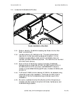
Router Installation in Hat Rack
3.3.1.
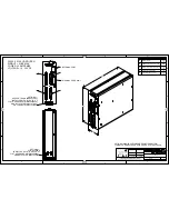
Refer to drawing G13006 for installing the Router into the “Hat
Rack” avionics shelf.
3.3.2. Location shown is for reference only. The exact placement is
dependent on other pre-existing equipment installed. It is the
installer’s responsibility to make sure this installation does not
interfere with other installed equipment. The router is to be mounted
Aft of the Fuel Cell area.
3.3.3. Note: for the G13160 Router replace in drawing G13006 the
following items: G13009 with G13161; G13009-3 with G13161-3;
G13006-2 with G13161-4 and use (3) MS24693S51 screws to
install; use (2) NAS622CE2 Support Hooks; Doubler G13006-4 with
G13161-5.
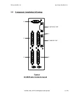
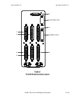
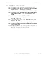
3.3.4. For Router G13000, refer to drawing G13004 for the detailed wiring
schematic used in this installation. For Router G13160, refer to
drawing G13162 for the detailed wiring schematic used in this
installation.
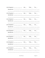
3.3.5. Be sure to carefully document the Radios and Control panels as
installed and their related connections for future maintenance and
troubleshooting purposes.
Summary of Contents for P139-HD
Page 2: ......
Page 4: ......
Page 5: ......
Page 6: ......
Page 7: ......
Page 8: ......
Page 16: ......
Page 17: ......
Page 19: ......
Page 22: ......
Page 23: ......
Page 24: ......
Page 26: ......
Page 27: ......
Page 28: ......
Page 29: ......
Page 30: ......
Page 31: ......
Page 32: ......
Page 33: ......
Page 34: ......
Page 58: ......
Page 60: ......
Page 62: ......
Page 64: ......
Page 78: ......
Page 80: ......
Page 82: ......


