Geneva Aviation, Inc.
www.GenevaAviation.com
GA182-8 Rev D P139-HD Digital Audio System
15 of 16
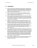
5.0 Load Analysis
5.1. At the completion of the installation of the audio system, the installer shall
perform a load analysis test of the electrical branch circuit that powers the
audio system, and also the entire aircraft electrical load, to confirm that the
addition of the audio system will not cause an overload to the electrical
branch circuit or the aircraft generator.
5.2. The current shall be measured using a properly calibrated ammeter. A
clamp-on amp meter, such as Amprobe Instrument model number ACDC-
600A, or equivalent will make this job easier.
5.3. Perform the branch circuit load analysis test by powering up all equipment
that is intended to be operated at the same time on the branch circuit that
the audio system is connected to. Additionally, key the three highest power
communication transmitters at the same time, if possible, while the current
measurements are being taken.
5.4. Measure the current of the branch circuit powering the audio system, by
clamping the meter around the branch circuit wire near its origin. Confirm
that the current draw during the above described test conditions is less
than the current limiter (fuse or circuit breaker) rating for that branch circuit.
5.5. If the current draw is greater than the current limiter rating, it becomes the
installer's responsibility to re-distribute some of the other equipment
powered by this branch circuit to another suitable branch circuit, in order to
reduce the load on the audio system's branch circuit to less than the
current limiter rating.
5.6. Once the branch circuit loads are within limits, test the current load for the
entire aircraft while all power for the aircraft is being supplied by the aircraft
generator, battery, or external power source. Perform this load analysis test
by powering up all equipment on the aircraft that is intended to be operated
at the same time as the audio system. Additionally, key the three highest
power communication transmitters at the same time, if possible, while the
current measurements are being taken. Clamp the ammeter around the
power source. Confirm that the current draw during the above described
test is less than the generator rating.
5.7. Upon satisfactory completion of these load analysis tests, make an aircraft
logbook entry that these tests have been performed satisfactorily in
accordance with this STC.
Summary of Contents for P139-HD
Page 2: ......
Page 4: ......
Page 5: ......
Page 6: ......
Page 7: ......
Page 8: ......
Page 16: ......
Page 17: ......
Page 19: ......
Page 22: ......
Page 23: ......
Page 24: ......
Page 26: ......
Page 27: ......
Page 28: ......
Page 29: ......
Page 30: ......
Page 31: ......
Page 32: ......
Page 33: ......
Page 34: ......
Page 58: ......
Page 60: ......
Page 62: ......
Page 64: ......
Page 78: ......
Page 80: ......
Page 82: ......

