Copyright © 2003-2005 Eagle Tree Systems, LLC
Page 8
magnet being in the right polarity. We have received problem reports of RPM reading errors when the RPM sensor is
mounted very near the magneto of spark engines, so we recommend mounting it 180 degrees away from the magneto, or as far away
as possible.
Installing the RPM Sensor
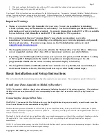
Once the magnets are glued and completely dry, temporarily position the RPM sensor so that
the side of the sensor with printing (or
a colored dot) is facing the side of the magnets WITHOUT the red line
. The sensor now needs to be glued so that it is held
rigidly into position. Before gluing, put a small spacer (1-2 mm thick) between the sensor and one of the magnets to ensure proper
spacing.
If desired, a small piece of brass tubing can be glued or heatshrunk to the back of the sensor to ease mounting and increase stability.
After the sensor is glued and completely dry, remove the small spacer and rotate the propeller to ensure complete freedom of
movement. Also make sure that the sensor won’t vibrate and come in contact with the magnets during driving. If this happens, the
sensor will be destroyed, and the Recorder could be damaged.
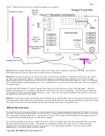
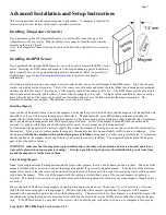
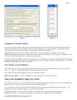
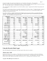
Once these steps are complete, plug the Futaba style connector on the sensor into the recorder as shown in figure 1. Note that a
standard Futaba style servo extension cable can be used to lengthen the wire if needed.
Using Existing RPM Sensors
Several of our customers have been able to use existing RPM sensors, such as governors or turbine sensors, with our products. The
following steps must be followed:
1)
Determine the “pinout” of the existing sensor. Compatible sensors will have Power, Ground, and Signal connections. The
Recorder’s RPM pinout, from left to right, is: Power (black wire), Ground (red wire), Signal (white wire).
2)
Devise a “Y” cable to connect your existing sensor to it’s connection, and also to the Recorder’s RPM connection. NOTE:
Power for the sensor should come only from the connection the sensor is normally plugged into. So, only Gound and Signal
wires should be routed from the existing sensor to the recorder. The power wire of the Y cable between the sensor and the
recorder should be cut before connecting it to the recorder. This is necessary to avoid connecting the power of the existing
sensor connection to the Recorder’s power connection.
3)
Thoroughly test the system to make sure the sensor still works with whatever it was originally connected to, after Y’ing to the
recorder.
Installing a Secondary RPM Sensor
A second MODIFIED RPM sensor can be plugged into the unused servo port nearest the switch on the recorder, for measuring RPM
of multiple motors. This RPM sensor must be modified by swapping the red and black wires in the RPM sensor plug. Carefully
pry back the plastic tabs that hold each pin in the plug, remove the red and black pins, and re-install them so that the pin order is RED,
BLACK, WHITE. The second RPM sensor plugs into the servo port with the red wire to the right, nearest the edge of the recorder.
The second RPM channel is automatically set up with the same gear ratio as the primary RPM.
The secondary RPM sensor is logged and displayed on the screens with the other parameters, as described below.
NOTE: When using a secondary RPM sensor in the servo port, servo port monitoring will not work correctly. It is a good idea to
select “Do not calibrate servos” in the New Model Wizard if you plan on using multiple RPMs.
NOTE: for the secondary RPM sensor to work, there has to be voltage from 4.5 to 6.5 V supplied to one or both of the servo inputs (as
shown in Figure 1). This is normally done with the optional Y Cables, a separate battery, or your BEC.
Connecting the Recorder to Your Aircraft’s Servos and Receiver
If you purchased the optional Servo ‘Y’ cables, you will be able to monitor your plane’s servo movements. The custom, heavy duty
‘Y’ cables with Universal connectors install in line between your throttle, rudder, aileron and elevator servos and your radio receiver.
Normally, when the servo ‘Y’ cables are installed, the system is powered by the receiver through the ‘Y’ cables. If you want to power
the Recorder from a separate battery, meaning that you want complete electrical isolation between the Recorder and your receiver, you
can power the Recorder with a small separate battery rather than using the optional Y cables.


