background image


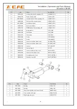
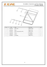
Installation, Operation and Parts Manual 

EE-6604 V2.BWF 


42


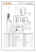
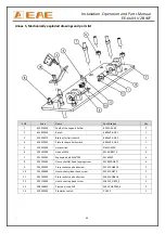
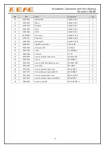
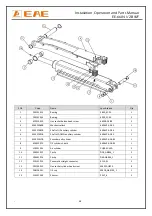
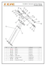
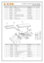
POS.


Code


Name


Specification


Qty


1


410250211


Ramp


shaft


6604V2

A4

B12


1


2


614025055


Ramp


6604V2

A9

B1


1


3


410250161


Ramp


wheel


shaft


of


the


JACK


6604V2

A9

B2


1


4


204301002


Circlip


D12_GB894_2


2


5


204301012


Circlip


D15_GB894_1


2


6


420180010


Small


wheel


MR30

A22

B5


2


Summary of Contents for EE-6604V2 .BWF

Page 1: ...issor lift Low Profile Electrical Leveling Lifting Capacity 4000KG Installation Operation and Parts Manual Distributed by Please read this entire manual carefully and completely before installation or...

Page 2: ...r and are protected against duplication and reproduction by copyright laws international agreements and other domestic legislation The reproduction or disclosure of instructions or an extract thereof...

Page 3: ...ruction of the lift 9 3 3 Dimensions 10 3 4 Safety device descriptions 11 3 5 Technical data 12 INSTALLATION INSTRUCTIONS 12 4 1 Preparations before installation 12 4 2 Installation attentions 13 4 3...

Page 4: ...checking essentially involves performing a visual inspection and a functional test This includes checking the condition of the components and equipment checking that the safety systems are complete a...

Page 5: ...o work near or under the vehicle Never remove safety related components from the lift Do not use if safety related components are damaged or missing 1 3 11 Do not rock the vehicle while on the lift or...

Page 6: ...re clearly depicted on the lift to ensure that the operator is aware of and avoid the dangers of using the lift in an incorrect manner The labels must be kept clean and they have to be replaced if det...

Page 7: ...crushing In the event of excessive vehicle weight incorrect mounting of the vehicle or on removing heavy object there is a risk of the vehicle falling off the lifting platform or tipping up Safety me...

Page 8: ...priate precautions never stack to more than 2 meters in height never make stacks of single packs Always stack pairs of packs in a cross pattern so that the base is bigger and the resulting stack is mo...

Page 9: ...works when power supply is connected and meanwhile oil in the pump pushes upwards the pistons of oil cylinders Thus scissor brackets of the lift rise accordingly The mechanical lock will automaticall...

Page 10: ...Installation Operation and Parts Manual EE 6604 V2 BWF 10 3 3 Dimensions...

Page 11: ...aused by break down of hydraulic system 3 24V operation voltage Safety voltage for operators 5 Max height limit switch for wheel jack Stop rising at a maximum height of 450mm above lifting platform 6...

Page 12: ...lifting platform for driving vehicles on and off To stop vehicles colliding with the ceiling it is advisable to fit an overhead light barrier in low ceiling buildings 4 1 2 Foundations and connections...

Page 13: ...you do not contact us and insist installing upon the lack of some parts we as well as our dealers will not bear any responsibility for this and will charge for any parts subsequently demanded by the b...

Page 14: ...oil Run the lift for several cycles and add another 4L into the tank The level of oil shall reach the tippets volume mark of the tank Run the lift for several cycles and add more oil until the lifting...

Page 15: ...d push UP button to check the synchronization Normally the two platforms are not synchronized till this step 5 If not being synchronized and one platform rises faster than the other open the levelling...

Page 16: ...ansion bolts 60 80N m 2 Rising speed 20mm s 3 Noise with rated load 75db 4 Grounding resistance not bigger than 4 5 Height difference of the two platform 5mm 6 Mechanical locks are robust and synchron...

Page 17: ...to the desired height switch off the power to prevent any wrong operation done by unconcerned people 5 1 6 Make sure the safety lock of the lift is engaged before start working under the vehicle and n...

Page 18: ...o raise vehicles Using the main lift Lifting capacity 4000KG Raise the lift Make sure vehicle is neither front nor rear heavy and center of balance should be centered over the lift 1 Drive and park th...

Page 19: ...ull out the extensions 3 Push UP button and check again if the rubber pads are directly under the pick up points of the vehicle when they are very close to the chassis 4 Keep on pushing UP button unti...

Page 20: ...ose or jammed Clean or adjust it The gear pump is damaged Replace it Oil level is too low Add oil The oil hose became loose or dropped off Tighten it The cushion valve became loose or jammed Clean or...

Page 21: ...ctions are in good condition Check whether the expansion bolts well anchored Check if safety teeth and safety block matched well or not 6 2 Weekly checking items Check the flexibility of moving parts...

Page 22: ...inimum thickness of 200mm Newly built concrete ground must be older than 20days 2 Concrete thickness of the base shall be more than 150mm and remove the peel offs in the bit 3 Flatness of the two base...

Page 23: ...Installation Operation and Parts Manual EE 6604 V2 BWF 23 2 Recessed Mounting...

Page 24: ...Installation Operation and Parts Manual EE 6604 V2 BWF 24 Annex 2 Electrical schemes and parts list...

Page 25: ...Installation Operation and Parts Manual EE 6604 V2 BWF 25...

Page 26: ...Installation Operation and Parts Manual EE 6604 V2 BWF 26...

Page 27: ...switch AR22PR 220B 1 SA2 320303009 Selection switch AR22PR 211B 1 QS 320304001 Power switch LW26GS 20 04 1 SB2 320401017 Button AR22F0R 20 W 1 SB1 SB3 SB4 320401019 Button AR22F0R 31 W 3 SB 320402002...

Page 28: ...AC contactor CJX2 1810 AC24V 1 C 321001004 Capacitor 4700UF 50V 1 VD 321002001 Bridge rectifier KBPC5A 35A 1 HL 321201001 Power indicator AD17 22G AC24 1 FA 321202001 Alarm buzzer AD17 22SM DC24 1 An...

Page 29: ...4 615025012 Main cylinder of the secondary lift 6604B A11 B1 1 5 410210011 Right angle connector 6603B A9 B4 1 6 615025014 Secondary cylinder of the secondary lift 6604B A12 B1 1 7 615018001 Right ang...

Page 30: ...4 16 624001815 Rubber oil hose 6 L 1700mm 1 17 410250271 Four way connector 6604B A29 1 18 624001819 Rubber oil hose 6R1AT L 4270mm 1 19 624001248 Rubber oil hose 6 L 3700mm 3 20 624001281 Rubber oil...

Page 31: ...18 330305002 Throttle valve 1 19 310101041 Three way connector 6604 TM14X1 5MT 3 20 310101042 Adjustable straight connector 6604 BJMSC G1 4 1 21 330307001 Two way ball valve GE2G1 4111AB 2 22 31010203...

Page 32: ...nnector KLL8 02 3 3 123010101 Air hose D 6 1 4 310201002 Silencer SLM02 R1 4 M12 1 5 310401001 Pneumatic solenoid valve 3V210 08DC24V 1 6 310101015 Quick straight air hose connector KLC8 02 1 7 123010...

Page 33: ...mit switch 6604V2 A1 B3 1 5 320301003 Limit switch D4MC 5020 1 6 203101009 Hex nut M16 M16 GB6170 4 7 201202001 Expansion bolt M16 120 M16X120 4 8 202205002 Hex socket flat head tapping screw M16X50 G...

Page 34: ...rame 6604V2 A2 B1 1 2 410253550 Pad plate for slider 6604V2 A2 B2 2 3 410253681 Pressure plate for Base B 6604V2 A2 B3 2 4 201202001 Expansion bolt M16 120 M16X120 4 5 202205002 Hex socket flat head t...

Page 35: ...25059B Outside support arm 6604V2 A3 B1 1 6 614025060 Inside support arm 6604V2 A3 B2 1 7 410252281 Mid shaft of support bracket 6604V2 A3 B3 1 8 410250061 Rotor wheel pad 6604V2 A3 B4 2 9 420250090 S...

Page 36: ...2 Cross socket flat head screw M6X16 GB819 4 23 202109021 Hex socket cylinder head screw M6X20 GB70 2 24 202101027 Cross socket cap head screw M6X8 GB818 2 25 208106002 Pressed oil cup M8 M8YP_GB7940_...

Page 37: ...le nylon slider 6605 A1 B8 4 19 204101006 Flat washer D10 D10 GB95 4 20 204301002 Circlip D12 GBT894_2 2 21 206201004 Cotter pin M3 45 2 22 202109050 Hex socket cylinder head screw M12X20_GB70 4 23 20...

Page 38: ...auxiliary cylinder 6604V2 A5 B4 1 6 410252391B Shaft of DOWN auxiliary cylinder 6604V2 A5 B5 1 7 615025017B Secondary oil cylinder 6604V2 A5B B1 1 8 614025070 Oil cylinder sheath 6604V2 A5B B2 1 9 310...

Page 39: ...2 205101054 Bearing 3030_SF 2X 2 3 205101026 Bearing 3525_SF 2X 2 4 205101034 Bearing 4030_SF 2X 4 5 410200111 Spacer 6503 A3 B4 4 6 615025004B Main oil cyliner 6604V2 A5 B1 1 7 615025017B Secondary...

Page 40: ...2111007 Hex socket flat head screw M8 20 M8X20_GB70_3 1 17 208106001 Oil cup M8YB_GB9740_1 2 18 208106002 Pressed oil cup M8 M8YP_GB7940_4 4 POS Code Name Specification Qty 1 205103003 Flange bearing...

Page 41: ...04101012 Flat washer D24 GB95 2 20 204301009 Circlip D25 GB894_1 4 21 204301011 Circlip D30 GB894_1 4 22 202109043 Hex socket cylinder head screw M10X30_GB70 4 23 202109080 Hex socket cylinder head sc...

Page 42: ...Code Name Specification Qty 1 410250211 Ramp shaft 6604V2 A4 B12 1 2 614025055 Ramp 6604V2 A9 B1 1 3 410250161 Ramp wheel shaft of the JACK 6604V2 A9 B2 1 4 204301002 Circlip D12_GB894_2 2 5 20430101...

Reviews: