Installation, Operation and Parts Manual
EE-6604 V2.BWF
-
18
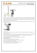
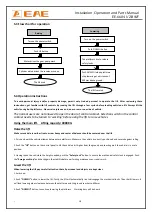
Turn
on
the
power
switch
Push
UP
button
Motor
drives
the
gear
pump
work
The
lift
rised
Cylinder
piston
drives
the
runway
move
up
The
platforms
rise
to
release
safety
locks
The
lift lowered
Push
DOWN
II
when
platforms
stop
lowering
at
a
distance
of
600mm
above
ground
Turn
on
the
power
switch
Push DOWN
I
button
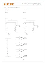
5.3
Flow
chart
for
operation
5.4
Operation
instructions
To
avoid
personal
injury
and/or
property
damage,
permit
only
trained
personel
to
operate
the
lift.
After
reviewing
these
instructions,
get
familiar
with
lift
controls
by
running
the
lift
through
a
few
cycles
before
loading
vehicle
on
lift.
Always
lift
the
vehicle
using
both
platforms
.
Never
raise
just
one
end,
one
corner
or
one
side
of
vehicle.
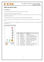
The
normal
users
are
not
allowed
to
open
the
door
of
control
cabinet.
Selection
switch
in
the
control
cabinet
needs
to
be
turned
to
‘working’
before
using
the
lift
to
raise
vehicles
.
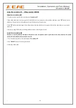
Using
the
main
lift.
Lifting
capacity:
4000KG
Raise
the
lift
Make
sure
vehicle
is
neither
front
nor
rear
heavy
and
center
of
balance
should
be
centered
over
the
lift.
1.
Drive
and
park
the
vehicle
midway
between
two
platforms.
Make
sure
the
vehicle
is
correctly
positioned
and
secured
against
rolling.
2.
Push
the
“UP”
button
on
the
control
panel
to
lift
the
vehicle
a
bit
higher
from
the
ground
and
check
again
if
the
vehicle
is
in
a
safe
position.
3.
Having
raised
the
vehicle
to
the
height
needed,
push
the
“Safety
Lock”
button
to
ensure
the
mechanical
safety
lock
is
engaged.
Push
the
“Emergency
Stop”
and
check
again
the
stability
before
performing
maintenance
or
repair
work.
Lower
the
lift
When
lowering
the
lift
pay
carefull
attention
that
all
personnel
and
objects
are
kept
clear.
1.
Switch
on.
2.
Push
”DOWN
I”
button
to
lower
the
lift.
Firstly,
the
lift
will
automatically
rise
to
disengage
the
mechanical
locks.
Then
the
lift
lowers.
It
will
stop
lowering
when
clearance
between
the
platforms
and
the
ground
reaches
to
600mm.
3.
Push
“DOWN
II”
button
to
continue
lowering
the
platforms.
Alarming
buzz
will
be
heard.
Raising
Lowering
Summary of Contents for EE-6604V2 .BWF
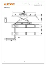
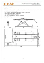
Page 10: ...Installation Operation and Parts Manual EE 6604 V2 BWF 10 3 3 Dimensions...
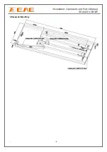
Page 23: ...Installation Operation and Parts Manual EE 6604 V2 BWF 23 2 Recessed Mounting...
Page 25: ...Installation Operation and Parts Manual EE 6604 V2 BWF 25...
Page 26: ...Installation Operation and Parts Manual EE 6604 V2 BWF 26...

