background image

                                                                  Installation,  Operation  and  Parts  Manual 


EE-65A.40T   


23 

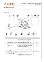
POS. 

Components   

Methods   

Period   

Safety lowering limit switch   

Push the DOWNI button. Inspect and ensure the lifting 

platform stops lowering at safety height and then push 

DOWN II button to have the platform fully lowered. 

Every day 

Control buttons   

Check if control buttons work as "hold- to -run " and 

check if they work as the function indicated.   

Every day 

10 

Solenoid unloading valve   

Inspect if the valve leaks or not. Clean or change the valve 

if it leaks.   

Every day 


Lifting platform 

Check and adjust the synchronization of lifting platforms. 

Ensure both platforms ascend and descend 

synchronously. 

Every day 

11 

Expansion bolts   

Check with torque spanner. For M18 bolt ,the torque is no 

less than 80N.m / For M16, the torque is no less than 

60N.m 

Every 3 months 

12 

Upside and downside sliders   

Add grease to ensure smooth running. 

Every 3 months 

13 

Joint shafts   

Add grease into the oil cups. 

Every 3 months 


Whole Lift   

Running the lift for several cycles with and without rated 

load. The lift can run steadily and smoothly with no 

abnormal noise.   

Every 3 months 


Hydraulic oil   

Change the oil 6 months after initial use and once per 

year thereafter. Inspect and change the oil if it becomes 

black or there is dirt in the oil tank. 

Every year 


If users stick to the above maintenance requirements, the lift will always keep a good working condition 
and its service life could be extended.   


Summary of Contents for EE-65A.40T

Page 1: ...s Manual Model No EE 65A 40T Short platform scissor lift Low profile Manual Levelling Lifting capacity 4000KG Please read this entire manual carefully and completely before installation or operation o...

Page 2: ...and are protected against duplication and reproduction by copyright laws international agreements and other domestic legislation The reproduction or disclosure of instructions or an extract thereof is...

Page 3: ...criptions 9 3 2 Construction of the lift 9 3 3 Dimensions 9 3 4 Safety devices descriptions 10 3 5 Technical data 11 INSTALLATION INSTRUCTIONS 11 4 1 Preparations before installation 11 4 2 Installati...

Page 4: ...pert or qualified person to perform checking It must be ensure that the person chosen satisfies the requirements The user bears special responsibility if employees of the company are appointed as expe...

Page 5: ...o lift the entire body of vehicles with its maximum weight within the lifting capacity 1 3 10 Always insure the safety locks are engaged before any attempt to work near or under the vehicle Never remo...

Page 6: ...clearly depicted on the lift to ensure that the operator is aware of and avoid the dangers of using the lift in an incorrect manner The labels must be kept clean and they have to be replaced if detac...

Page 7: ...rushing In the event of excessive vehicle weight incorrect mounting of the vehicle or on removing heavy object there is a risk of the vehicle falling off the lifting platform or tipping up Safety meas...

Page 8: ...able use all appropriate precautions never stack to more than 2 meters in height never make stacks of single packs Always stack pairs of packs in a cross pattern so that the base is bigger and the res...

Page 9: ...nvenience Its platform extension deign not only can be used as a ramp but also can serve as an extended part of the platform for much longer vehicles Besides designs like 24V working voltage of contro...

Page 10: ...eight of 1930mm above the ground 3 Safety lowering height limit switch The lifting platforms automatically stop lowering at safety height above the ground It needs to push DOWN II button to continue t...

Page 11: ...struction of the foundation following consultation with the manufacturer s customer service or an authorized service agent Routing of the wiring to the installation location The user must provide fuse...

Page 12: ...Installation Operation and Parts Manual EE 65A 40T 12 Surface mounting...

Page 13: ...on Qty Electrical drill With D16 and D18 drill bit 1 Open spanner D17 19mm 2 Adjustable spanner bigger than D30mm 1 Cross socket screw driver PH2 1 Quick spanner handle adapter Ratchet 1 Socket spanne...

Page 14: ...l wires 4 2 2 All bolts should be firmly screwed up 4 2 3 Do not place any vehicle on the lift in the case of trial running 4 3 General Installation Steps Step 1 Dismantle the package of the lifting p...

Page 15: ...oses and do not contaminate the hydraulic components during the connection Step 5 Connect the electrical system Refer to Annex 1 when fix the electrical system Connect the wire connectors for raising...

Page 16: ...raising or lowering Open one of the levelling valves and push the UP button to supplement oil to the oil hose connected Turn off the valve to stop adding oil In normal working condition both levelling...

Page 17: ...ving been turned off push the UP button to check if both platforms rise synchronously A 7 Repeat doing step A5 and step A 6 until synchronization achieved Step 9 Fix base frames with expansion bolts 1...

Page 18: ...anical locks are robust and synchronized when running with rated load 7 If the control button works as hold to run 8 If limit switches work well 9 If grounding wire is connected 10 If the lift rises a...

Page 19: ...d height switch off the power and lock the button with a padlock to prevent any wrong operation done by unconcerned people 5 1 6 Make sure the safety lock of the lift is engaged before start working u...

Page 20: ...ake sure that you have read and understood the operation manual before operation 2 Drive and park the vehicle midway between two platforms 3 Place the four rubber pads under the pick up points of the...

Page 21: ...screwed up or jammed Clean or make adjustment Damaged gear pump Replace it Too low oil level Add oil The hose connection is loose Tighten it The motor run reversely Check the wire connection Platforms...

Page 22: ...ders and oil hose connectors Inspect to ensure no leakage before using the lift Every day 3 Pneumatic filter Listen and inspect if it leaks or not Inspect and ensure the the water level is below its m...

Page 23: ...orms ascend and descend synchronously Every day 11 Expansion bolts Check with torque spanner For M18 bolt the torque is no less than 80N m For M16 the torque is no less than 60N m Every 3 months 12 Up...

Page 24: ...lation Operation and Parts Manual EE 65A 40T 24 Annex 1 Electrical schemes and parts list Note For the specific requirements on voltage the actual voltage of your lift may differ with the following di...

Page 25: ...Installation Operation and Parts Manual EE 65A 40T 25...

Page 26: ...Installation Operation and Parts Manual EE 65A 40T 26...

Page 27: ...mergency stop XB2BS542C 1 320503002 Ground terminals 4 1 320505006 Wire terminals VK 5N UK 5N 9 KA1 KA2 320601001 Relay HH54P L DC24V MY4NJ 2 320601011 Relay holder PYF 14A E 2 320601018 Relay feet fi...

Page 28: ...Dust proof ring DHS50 50 58 6 1 POS CODE Name Specification Qty 1 207103032 Y seal ring B7 75 60 9 1 2 207105007 Dust proof ring DHS50 50 58 6 1 1 18L oil tank 2 Oil sucking filter 3 Gear pump 4 Coup...

Page 29: ...5 624001898 Rubber oil hose 6 2 L 900 1 6 624001062 Rubber oil hose L 1650mm 1 7 624001130 Rubber oil hose 6 2 L 200 1 8 410210181 Three way connector 6603B A9 B7 1 9 624001062 Rubber oil hose L 1650m...

Page 30: ...nnector M14 1 5 G1 4 2 5 201102002 Hex flange screw M5 10 4 6 202109064 Hex socket cylinder head screw M6 30 4 7 207103019 Composite washer M14 6 8 330101007 Hydraulic block YF 4 1 9 320201001 Motor 2...

Page 31: ...tube YH D 1 18 330404001 Coupling YL A 1 19 330403001 Oil sucking filter YG C 1 20 330201005 Gear pump assembly CBK F220 CBK 2 1F 1 3Ph 2 2kW 20 330201004 Gear pump assembly CBK F216 1 1PH 2 2kW Annex...

Page 32: ...65A40 A1 B2 1 3 410197281 Roll shaft of base plate 65A40 A1 B3 4 4 204301009 Circlip M25 8 5 410650203 Hose protective slot 65A40 A1 B4 1 6 208106002 Pressed oil cup M8 4 7 202101022 Cross socket cap...

Page 33: ...8 1 20 202301008 Cross socket cap head tapping screw ST4 8 35 22 21 121010103 Plastic expansion tube M10 40 22 22 201201011 Expansion bolt 10 100mm 4 23 614065003 Fixed ramp 65A40 A7 B1 2 Pos CODE Nam...

Page 34: ...40 A2 B15 2 25 614065009B Safety locking teeth 65A40 A4 B1 2 26 614065010 Sheath of the safety lock 65A40 A4 B2 2 27 410197031 Pin shaft D of the arm 65A40 A2 B6 4 28 410197061 Pin shaft A of the arm...

Page 35: ...nder head screw M6 15 4 59 420210060B Padding block 6603B A5 B6 4 60 420650020 Limitation slider 65A40 A2 B19 1 61 410650041 Downside plate for limit switch 65A40 A2 B17 1 62 202101008 Cross socket ca...

Page 36: ...7 410197301 Platform installation plate 65A40 A5 B5 2 8 202111005 Hex socket flat head screw M8 15 8 9 206101010 Inside swivel post pin D8 16 4 10 614065014 Supporting rod 65A40 A5 B4 2 11 614065013...

Page 37: ......

Reviews: