


16
The SCS200 has an integral CAN terminationi as a standard set-up. This could also be the case with devices made by
other manufacturers. Please make sure to always provide sufficient CAN termination.
Upon request, the SCS200 is also available without integral CAN termination (see ordering information in the SCS200
data sheet).
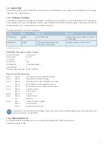
The SCS200 supports a bit rate of 250 kbps.
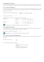
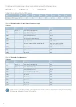
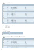
7.2 Data format
The SCS200 sends information, including diagnostic and measuring data, which are longer than one byte. These data are sent first
within the CAN message according to SAE J1939-71 with Least Significant Byte (LSB).
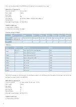
PGN Position Notation Start Position
Length
1-4
4 bytes
(ex. PGN 65199, SPN 1039)
01-04
4 bytes
(ex. PGN 65211, SPN 994)
Data Definition
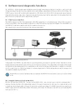
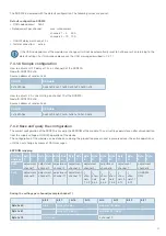
7 CAN communication
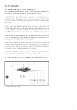
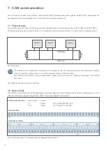
The CAN communication of the SCS200 is based on the CAN 2.0B specification and supports the SAE J1939. The product can
be integrated into a corresponding CAN system with other standard components.
7.1 Physical layer
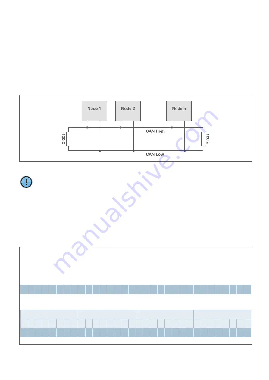
For a reliable communication, the CAN physical layer should be built up to the specifications of ISO 11898-2 or SAE J1939-1x.
Wiring should only be at each end of the bus as a twisted pair with terminating resistors in a »daisy chain« arrangement (fig. 7).
fig. 7: CAN network
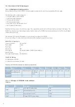
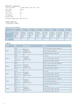
fig. 8: Transmission sequence of several data bytes (not alphanumerically) to J1939-71
b32 b31 b30 b29 b28 b27 b26 b25 b24 b23 b22 b21 b20 b19 b18 b17 b16 b15 b14 b13 b12 b11 b10 b9 b8 b7 b6 b5 b4 b3 b2 b1
MSb
Byte 1
LSb MSb
Byte 2
LSb MSb
Byte 3
LSb MSb
Byte 4
LSb
8
7
6
5
4
3
2
1
8
7
6
5
4
3
2
1
8
7
6
5
4
3
2
1
8
7
6
5
4
3
2
1
b8 b7 b6 b5 b4 b3 b2 b1 b16 b15 b14 b13 b12 b11 b10 b9 b24 b23 b22 b21 b20 b19 b18 b17 b32 b31 b30 b29 b28 b27 b26 b25
MSb
MSb
LSb
LSb
Transmission Order


