background image


M500 USER MANUAL AND PROGRAMMER SDK 


Page 20 


9.


C#


API 

The C# API provides a simple interface to the M500.  The C# developer should be able to use this interface 
to quickly interface  with the  M500 without  needing to interface with the M500 DLL unmanaged code 
directly. 


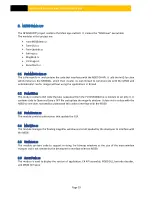
The DLL creates its own thread to poll the M500.  The application should register for call back    events at 
initialization.  The DLL will then call back the application on the DLLs thread when an event occurs.  The 
application  should  then  synchronize  the  call  back  to  its  thread  using  the  Invoke  method  in 
FormM500demo.cs. 


9.1


API


F

UNCTIONS


void 

SetLogDir

(LOG_DIR)  [Optional] 

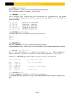
Call this function before Init() to override the default log directory.  By default if this function is not called 
the M500DLL will create the M500DLL.LOG file in the same directory it is running in. Pass this function the 
string of the desired log directory.  To disable logging pass the string “null”.   

void 

AutoFwUpgrade

(bool bAuto) 

Call this function with false before Init() to override the default behavior (as of version 1.9) of automaticaly 
updating the M500’s firmware if it is out of date.   You do not have to call this function if you want the 
default behavior of automatic firmware upgrade. 

void 

Init

()


Call this function at initialization such as during form load. 

void 

RegCB

(OnNewEvent) 

Register event call back. 

void 

LastScan

(iLastScan) [Optional] 

By default, cards are scanned using white, IR, and UV light. 
To override the last scan pass iLastScan with the folling values after the RGB image is ready: 

0 = 

RGB-IR-UV (normal) 

3 =   RGB only 

void 

Close

() 

Call this function before closing the application such as during form closed. 
 

void 

ClearData

(byte byGrey) 

Call this function to clear the bitmap images, barcode, and magnetic stripe data.  There is no need to do 
this under normal circumstances but an application may wish to do this to after the scanned data has 
been processed for maximum privacy. 
 
The byte passed to ClearData() will be copied to every 24bit RGB pixels. 
Passing 0 will results in black bitmaps (until the next scan)  
Or passing 0x80 will result in medium gray. 

Summary of Contents for M500

Page 1: ...M500 User Manual and Programmer SDK Revision 1P Doc No 560802 1A May 19 2017...

Page 2: ...on system apparatus machine material method or process in which E Seek products might be used An implied license only exists for equipment circuits and subsystems contained in E Seek products E Seek a...

Page 3: ...starting the scanner 10 3 1 3 Upgrade firmware from User application 10 4 RUNNING DEMO APPLICATION 11 5 SCOPE 11 6 OPERATION 11 6 1 INDICATOR LEDS 11 6 2 EJECT BUTTON 12 6 3 GUI 12 6 3 1 Small Image P...

Page 4: ...M500 USER MANUAL AND PROGRAMMER SDK Page 3...

Page 5: ...ety or in part is strictly prohibited The information contained in this User s Guide is subject to change without notice 1 1 PRODUCT FEATURE This device is an ID card authentication system that perfor...

Page 6: ...M500 USER MANUAL AND PROGRAMMER SDK Page 5 2 1 OVERVIEW OF MODEL M500 Figures 1 and 2 illustrate the major modules and components of the M500 Figure 1 Figure 2...

Page 7: ...ower status Blue and White center mounted LEDs under user control Red LED for Error status Communication High Speed USB 2 0 Weight M500 device 4 25 lb Without Power Supply Dimensions 8 5 Length x 5 7...

Page 8: ...wer Supply USB Cable Cleaning Card Calibration Card Power Supply The AC DC power supply The power cord plugs into the power jack Figure 3 2 4 1 USB CABLE The M500 is provided with a USB interface cabl...

Page 9: ...he white balance calibration simply insert the card with the arrow side first After prolonged use or if the card becomes scratched it should be discarded 2 4 3 CLEANING CARD Figure 6 The cleaning card...

Page 10: ...nstalling the 32 bit Driver for Windows 32 bit XP Vista 7 and 8 Run M500_USB_DRIVER 32 exe Installing the 64 bit driver for Windows 64 bit Vista 7 and 8 Run M500_USB_DRIVER 64 exe WinDriver should app...

Page 11: ...e or downgrade the firmware in M500dll dll Step 1 Connect the M500 to PC and run your application which loads M500dll dll Step 2 Unplug the power to the M500 Step 3 Press and hold the Eject button loc...

Page 12: ...USB The PC software also includes a third party USB driver from Jungo This document covers the M500 C sample application and the C API that gives a C developer a simple interface to the unmanaged C C...

Page 13: ...BUTTON This button which is located on the top of the units is used to try to eject a jammed card 6 3 GUI Figure 9 The GUI has a toolbar and controls on the top small preview images on the left a larg...

Page 14: ...n image with the right side illuminate using IR light and detected on the left side which is not illuminated The intensity of the bleed through image is an indication of the card s opacity The big ima...

Page 15: ...white LED mounted next to each other Clicking on this button cycles thru blue LED on white LED on blue LED blinking white LED blinking and both LEDs off Note that early production units do not have a...

Page 16: ...M500 USER MANUAL AND PROGRAMMER SDK Page 15 6 3 3 SCAN MODES By default the normal scan mode is RGB IR UV Click on the Scan Normal button until it changes to Scan RGB for fast RGB only scanning...

Page 17: ...er versions and brings up a dialog box if the versions do not match The T1 T2 and T3 likewise will turn green when data is found on the magnetic stripe for tracks 1 2 3 6 3 5 STATUS BAR The triangle i...

Page 18: ...mismatch or other serious error it will sends an error event In this case EV_ERR_FW_VER and send a command to the firmware to flash its red LED On receiving this event the demo application will pop u...

Page 19: ...API The application M500 exe or user application M500api dll M500dll dll and SD2 dll must be in the same directory The DLL will create a log file M500dll log in the directory in which it is running by...

Page 20: ...ule contains GUI code that was separated from the FormM500demo cs module to simplify it It contains code to Open and Save a TIFF file and update the magnify window It does not interface with the M500...

Page 21: ...ade bool bAuto Call this function with false before Init to override the default behavior as of version 1 9 of automaticaly updating the M500 s firmware if it is out of date You do not have to call th...

Page 22: ...ration has three values BEEP_1 BEEP_2 BEEP_3 bool EjectCard Starts the card eject procedure as if one had pressed the eject button This allows the application to try to eject a stuck card without the...

Page 23: ...freshes the APIs bitmaps barcode and magstripe data from an M500 tif file bool WrUserData byte aryData Writes a user data byte array to flash 128 byte limit Flash should not be used store frequetly ch...

Page 24: ...ANCEL Scan aborted EV_DOOR_OPEN Door opened EV_DOOR_CLOSE Door closed EV_CLEAN_CARD Cleaning card EV_WHITE_CAL White calibration card EV_WHITE_CALV White card verification in reverse for dust detectio...

Page 25: ...first two images are the RGB front and back The next two images are the IR front and back The last two main images are the UV front and back The last image is a low resolution IR bleed image captured...

Page 26: ...Front is on the left 4 Front is on the left and upside down The main element of the 2D barcode structure is the length zero if not decoded unsafe public struct BC_2D public short nLen Length After ge...

Page 27: ...MsRdy on applications thread break case EV_RGB_RDY Invoke new MethodInvoker ScanRgbRdy RGB image ready break case EV_BC_RDY Invoke new MethodInvoker EvScanBcRdy Barcode ready break case EV_IR_RDY Invo...

Page 28: ...se of the White Calibration Card feedback in the determination of whether or not dust or debris may have accumulated on the M500 s mirrors The Verification Process occurs when the Calibration Card is...

Page 29: ...ic part made to block the M500 scan path and divide the air flow Item M500 AIRDV 3 Air Duster aerosol can of compressed air The preferred air duster is designed to leave no residue with a high filtrat...

Page 30: ...the M500 side door and insert the Plastic Air Divider Air Divider Plastic insert 1 Insert the Air Divider down inside the M500 into the opening 2 Position the Air Divider under the top spring loaded...

Page 31: ...ime ignore the Right side image Step 6 Calibration At this point you need to calibrate the M500 without any dust present on the mirrors This is a simple and mostly automatic process Simply insert the...

Page 32: ...M500 USER MANUAL AND PROGRAMMER SDK Page 31 10 3 MECHANICAL DRAWING...

Reviews: