OPERATION
2-3
September 2001
Part No. 001-5100-001
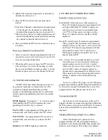
Figure 2-1 Front Panel Controls
Speaker
Display
DTMF Keypad
Option Keys
Microphone
Full Keypad Model
Limited Keypad Model
Up/Down Sw
Option Keys
2.3.2 TOP PANEL CONTROLS
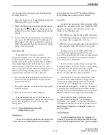
Two-Color Indicator -
Indicates the following
conditions:
Steady Red - Transmitter keyed, normal power.
Flashing Red - Transmitter keyed, low battery (the
low power mode is automatically selected).
Steady Green - Carrier detected in receive mode.
Flashing Green - Low battery in receive mode. In
addition, when scanning, it flashes when the prior-
ity channel is scanned while receiving a message
on a non-priority channel.
Option Switch -
This is a three-position toggle switch
that can be system operator programmed to control
some function (see Section 2.2).
On-Off/Volume -
Turning the knob clockwise turns
power on and sets the volume level. Turning it coun-
terclockwise to the detent turns power off.
Figure 2-2 Top Panel Controls
Emergency
(Option)
On-Off
Volume
Channel
Switch
Antenna
Connector
Option
Sw
Switch


