background image

TRANSCEIVER PROGRAMMING

3-16

September 2001

Part No. 001-5100-001

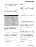
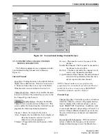
Figure 3-3   Conventional Analog Channel Screen

3.5.6 CONVENTIONAL ANALOG CHANNEL 

SCREEN PARAMETERS

The following parameters are programmed in the 

Conventional Analog Channel screen shown in 
Figure 3-3.

Selected Channel

Zone Box - Clicking the arrow to the right of this box 
displays the available zones. Click on a zone to select 
it. Zones and zone aliases are set up on the Radio- 
Wide General screen described in Section 3.4.2.

Channel Index Box - Displays the available channels 
in the selected zone. The channel type is selected by 
the Channel Type box below it.

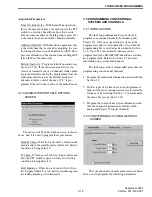
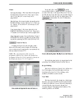
 Modify Button - Displays the Modify 

Channel List screen also shown in Figure 3-3. This 
screen enables the channel (makes it selectable) and 
programs the following channel parameters: 

Channel - Selects the channel to be edited.
Alias - Programs the identification that is displayed 

when the channel is selected. Up to 10 
characters can be programmed. 

Transmit - Programs the transmit frequency of the 

channel. 

Receive - Programs the receive frequency of the 

channel.

Enable This Channel - The box must be checked for 

the channel to be selectable. 

Rx Only - The box is checked if the channel is to be 

receive only (transmitter disabled). 

Copy Parameters From Channel - If another channel 

is selected, the parameters from that chan-
nel are copied to the new channel.

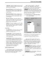
NOTE: Channel numbers not assigned must be 
programmed for conventional operation and then not 
enabled in the above screen because SMARTNET/ 
SmartZone channels cannot be disabled.

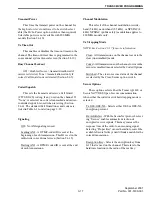
Channel Type

Channel Type Box - Selects the specific system from 
which the channel is selected. All programmed sys-
tems are displayed by number and type (conven-
tional, SMARTNET, SmartZone). In addition, with 
conventional channels, either analog or Project 25 is 
selected. When a different channel type is selected, 
the screen for that type of channel is automatically 
displayed. 

System Specific Information - With conventional 
systems, indicates the frequency of the selected 
channel without having to select the Modify box.

Summary of Contents for 5100 SERIES

Page 1: ...Service Manual ual 5100 SERIES PORTABLE DIGITAL ANALOG VHF UHF 800 MHz 7 2 VDC 5 1 W VHF 4 1 W UHF 3 W 800 MHz Part No 242 51xx xxx First Printing September 2001 PRELIMINARY ...

Page 2: ...adio products E F Johnson is a wholly owned subsidiary of Transcrypt International Inc Viking Head EFJohnson logo Call Guard PCTrunk and PCTune are registered trade marks of the E F Johnson Company SMARTNET SmartZone SecureNet Call Alert Enhanced Private Conversation and Private Conversation II are trademarks of Motorola Inc All other company and or product names used in this manual are trademarks...

Page 3: ... 8 Standard Scanning 2 8 Radio Wide Scanning 2 8 Scan Resume Delay 2 9 Standard Mode Scan List 2 9 Radio Wide Mode Scan List 2 9 Determining Which Channels are in Scan List 2 9 Nuisance Channel Delete 2 9 Programming a Scan List 2 9 2 6 CONVENTIONAL FEATURES 2 10 Introduction 2 10 Display Mode Selection 2 10 Monitoring Before Transmitting 2 10 Monitor Mode 2 11 Busy Channel Lockout 2 11 Call Guard...

Page 4: ...alog Channel Screen Parameters 3 16 Conventional Project 25 Digital Channel Screen Parameters 3 18 3 6 PROGRAMMING SMARTNET SMARTZONE SYSTEMS AND CHANNELS 3 19 Introduction 3 19 SMARTNET SmartZone System General Screen 3 19 SMARTNET SmartZone System Other ID s Screen 3 20 SMARTNET SmartZone System Phone Interconnect Screen 3 20 SMARTNET SmartZone System Talk Groups Screen 3 21 SMARTNET SmartZone S...

Page 5: ...oard Layout 8 4 800 MHz RF Board Schematic 8 5 800 MHz RF Board Layout 8 6 Logic Board Rev 3 Schematic 8 7 Revised Keypad Board Schematic 8 8 LIST OF FIGURES 2 1 Front Panel Controls 2 3 2 2 Top Panel Controls 2 3 2 3 Keypad Programming Flowchart 2 26 3 1 Programming Setup 3 1 3 2 Main Screen Later PCTrunk Versions 3 3 3 3 Conventional Analog Channel Screen 3 16 3 4 Conventional Project 25 Digital...

Page 6: ...sed in systems where the channel spacing is 25 kHz or 30 kHz Project 25 Digital Operates on Project 25 compatible systems The voice is digitized error corrected optionally encrypted and then transmitted using C4FM modulation according to the Project 25 stan dard This mode uses a channel spacing of 12 5 kHz 1 2 3 OPERATING PROTOCOLS The 5100 series transceivers can be programmed for all the followi...

Page 7: ...conventional or SMARTNET SmartZone For example a zone could include 12 conventional chan nels and 4 SMARTNET channels Zones are similar to banks used in other E F Johnson transceivers One use of zones may be to program the channels used for operation in a specific geographical area Up to 16 zones can be programmed 1 2 6 SECURE COMMUNICATION Secure communication is available with all the preceding ...

Page 8: ...iver identification number is printed on a label that is attached to the chassis The following information is contained in the identification number 1 6 ACCESSORIES The accessories available for this transceiver are listed in Table 1 1 A brief description of some of these accessories follows Battery NiCd The 1500 mAH nickel cadmium battery provides up to 8 hours of operation at a 5 5 90 duty cycle...

Page 9: ...m You need to know the name of the person you want to reach Example jsmith efjohnson com NOTE Emergency 24 hour technical support is also available at the 800 and preceding numbers during off hours holidays and weekends When your call is answered at E F Johnson you will hear a brief message informing you of numbers that can be entered to reach various departments This number may be entered during ...

Page 10: ...use there are times when the technicians have specific questions that need to be answered in order to completely iden tify and repair a problem When returning equipment for repair it is also a good idea to use a PO number or some other reference number on your paperwork in case you need to call the repair lab about your unit These numbers are refer enced on the repair order and it makes it easier ...

Page 11: ...0 kHz Frequency Stability 1 5 PPM 22 to 140 F 30 to 60 C Dimensions w o antenna 6 7 H x 2 52 W x 1 9 D 17 0 cm x 6 4 cm x 4 8 cm Weight w std battery 24 oz 675 g Supply Voltage 7 5 volts DC nominal Battery Life 8 hours typical w std 1500 mAH NiCd battery Current Drain maximum Standby 110 mA Receive rated audio out 350 mA Low Tx Power 1 2 A High Tx Power 2 6 A 800 MHz 2 4 A VHF UHF RECEIVER Sensiti...

Page 12: ...II and Telephone Calls Emergency alarms to alert dispatcher of emergency conditions Emergency calls for high priority system access Failsoft operation on a predefined conventional channel if trunked system fails Priority group calls detected while listening to other group calls Call Alert send and receive pages Predefined messages up to 16 can be sent to a dispatcher Predefined status conditions u...

Page 13: ... The transceiver speaker is located behind this grill When a speaker microphone is used this speaker is automatically disabled Microphone The microphone is located in this area For best results hold the transceiver 2 3 inches from you mouth and speak at a normal conversational level Front Display This is an 8 character 14 segment LCD Liquid Crystal Display This display backlight can be programmed ...

Page 14: ...ed Steady Green Carrier detected in receive mode Flashing Green Low battery in receive mode In addition when scanning it flashes when the prior ity channel is scanned while receiving a message on a non priority channel Option Switch This is a three position toggle switch that can be system operator programmed to control some function see Section 2 2 On Off Volume Turning the knob clockwise turns p...

Page 15: ...ries such as a speaker microphone 2 3 4 DISPLAY The front panel display is shown above In the conventional mode if the Display Information option switch is programed either the channel number channel name or frequency can be selected see Section 2 6 2 The following information is indicated in the display Alphanumeric Characters These eight characters indicate the selected channel error conditions ...

Page 16: ...witch unsquelches squelches the receiver and either voice or background noise is heard If a SMARTNET SmartZone channel is selected the receiver cannot be manually unsquelched 2 4 3 POWER UP PASSWORD General The power up password feature prevents unau thorized use of the transceiver When it is enabled by system operator programming an eight digit password must be entered to make the transceiver ope...

Page 17: ... When the battery voltage falls below a preset level the radio can be programmed so that any or all of the following indications occur The indicator on the top panel flashes red in the transmit mode and green in the receive mode A chirp sounds every 5 seconds in the receive mode A chirp sounds every 5 seconds in the transmit mode The battery should be recharged as soon as prac tical after a low ba...

Page 18: ...the on or off mode by programming 2 4 12 TRANSCEIVER OPERATING MODES Introduction Each selectable channel can be programmed for either the conventional or SMARTNET SmartZone operating mode For example Zone 1 Channel 1 could be a conventional channel Zone 1 Channel 2 a SMARTNET channel and so on More information on these modes follows Conventional Mode This is a non trunked operating mode which acc...

Page 19: ...e is the same regardless of the channel type selected Only one of these scan modes can be enabled at a time Therefore if standard scanning is enabled while radio wide scan ning is occurring radio wide scanning is automatically disabled and vice versa More information on these modes follows 2 5 2 STANDARD SCANNING Standard scanning monitors only channels that are the same type as that currently sel...

Page 20: ... are not indicated With conventional channels the selected channel is in the current scan list if SL Scan List is indicated in the upper part of the display 2 5 8 NUISANCE CHANNEL DELETE With standard scanning channels can be tempo rarily deleted from the scan list for example if messages on a channel become annoying This feature is not available with radio wide scanning Proceed as follows NOTE Th...

Page 21: ...n 2 4 12 Refer to Section 2 4 for information on features common to all operating modes and to Section 2 7 for information on features unique to the SMARTNET SmartZone mode 2 6 2 DISPLAY MODE SELECTION If the Displayed Information option switch is programmed it is usually the three position toggle switch on the top panel This switch selects the following conventional channel display modes If this ...

Page 22: ...e sounds until the PTT switch is released The transceiver can be programmed to operate in one of the following modes on each channel Off Busy channel lockout is disabled and the trans mitter keys even if the channel is busy Noise The transmitter is disabled if a carrier is detected on the channel Tone The transmitter is disabled if an incorrect Call Guard CTCSS DCS or NAC code is detected see Sect...

Page 23: ...as been enabled by programming the transmit and receive codes from one channel can be temporarily or perma nently reassigned to all channels of the current zone Proceed as follows 1 Using the number keys enter the number of the channel that is programmed with the code you want to reassign to all channels only channels 1 9 can be selected See Section 2 6 2 for information on displaying channel numb...

Page 24: ...transmissions occur on the selected channel If an analog channel is selected and scrambling is programmed pressing the Emergency switch sends an emergency signal on the selected channel 20 times or until an acknowledgment is received Keying the radio also cancels the emergency condition If a Project 25 digital channel is selected pressing this switch selects the emergency mode and if the PTT switc...

Page 25: ...ogrammed by the following parameters Lookback Time A This time determines how often the priority channel is checked for activity Times of 0 25 4 00 seconds in 0 25 second steps can be programmed Lookback Time B This time determines how often the priority channel is checked once an incorrect Call Guard CTCSS DCS or NAC code is detected Since it takes much longer to detect an incorrect Call Guard si...

Page 26: ...All DTMF signaling is disabled 2 6 16 PROJECT 25 MODE FEATURES Individual Group and NAC Codes Individual ID Each transceiver that operates on Project 25 digital channels is programmed with an 8 digit individual ID This ID is unique for each transceiver and can be any number from 1 16777216 When power is turned on with a Project 25 channel selected this ID is briefly displayed Group ID Each Project...

Page 27: ...onventional analog channels SecureNet and 460 scrambling More information on these protocols follows SecureNet SecureNet is a proprietary Motorola protocol that digitizes the voice and then encrypts it using the DES algorithm It provides the highest level of security There are two DES protocols DES CFB uses cipher feedback DES encryption A disadvantage of this type is reduced communica tion range ...

Page 28: ...itch between the clear and secure mode at any time using the Clear Secure option switch SecureNet signals are unintelligible when 460 scrambling is used and vice versa With the SecureNet protocol the following receive options can be programmed No Autodetect Only signals coded like the transmit signals are received Secure Autodetect Both clear and SecureNet signals are automatically detected This m...

Page 29: ...made to change from the secure to the clear mode and this is not permitted SEC ONLY is displayed and the call continues in the secure mode Receiving a Standard Call When a SMARTNET SmartZone group call is received the transceiver can be programmed to display the Individual ID of the calling mobile and or the received talk group alias The Individual ID is briefly displayed when the call is received...

Page 30: ...call by pressing the CLR key If neither your radio nor the radio being called is authorized to make unit to unit calls REJECT is displayed and a continuous tone sounds End the call by pressing the CLR key If the called party answers but the radio system is busy four low tones sound and BUSY is displayed When the system is no longer busy the call back tone sounds If in the secure mode and your tran...

Page 31: ...he Private Call option switch until a tone sounds approximately 1 second The last ID called is displayed 2 Using the 0 9 keys enter the ID all six digits of the mobile unit you are calling To erase the last digit press the key and to cancel the call press the CLR key 3 Press the PTT switch to initiate the call If the entered ID did not contain six digits INVALID is momentarily displayed an error t...

Page 32: ...hod for conditions that may then occur Direct Entry Method Full Keypad Models Only 1 With a SMARTNET SmartZone channel selected press and hold the Phone option switch until a tone sounds approximately 1 second The display indi cates the alias of the last called telephone number if it is in your phone number list Otherwise the last eight digits of the last called telephone number are displayed 2 En...

Page 33: ...nly List Entry Method 1 With a SMARTNET SmartZone channel selected momentarily press the Call Alert option switch The tag alias of the last ID called is displayed if it matches an ID in your call list Otherwise the last ID called is displayed 2 Enter the index of the desired ID if you know it or scroll through the list using the and keys until you find the desired ID Press the CLR key to cancel th...

Page 34: ... status sent is displayed 2 To change the displayed status enter the index of the desired status if you know it or scroll through the list using the and keys until you find the desired status Press the CLR key to cancel this function 3 Press the PTT switch to send the status When the message is received and acknowledged by the dispatcher a signaling success tone six beeps sounds and the display re...

Page 35: ...sages on the priority channel are received while listening to lower priority messages However private and telephone calls are not inter rupted by calls on the priority channel When responding to messages in the scan mode programming determines if the response always occurs on the talk group of the call or the selected talk group if they are different Transmissions occurring at other times always o...

Page 36: ...llowing calls require their own encryption key selection emergency failsoft patch telephone private and system wide 2 8 SUPERVISORY TONES Single Beep Alert Tone Power was turned on and a successful power up sequence occurred see Section 2 4 2 The time out timer is about to expire or the penalty timer has expired Sections 2 4 10 and 2 6 7 The conversation timer is about to expire Section 2 6 8 The ...

Page 37: ...able after a busy condition occurred SMARTNET SmartZone only 2 9 KEYPAD PROGRAMMING 2 9 1 INTRODUCTION Keypad programming is available with full keypad 18 key models if the Keypad Programming option switch is programmed It is then selected by pressing this switch and entering the programming password This password is a series of eight digits selected preprogrammed using PCTrunk and it prevents una...

Page 38: ...increment the timer in 30 second steps 0 disables it When the desired value is displayed store it by pressing the ENT F4 key 2 9 5 CHANNEL PROGRAMMING Zone Selection The zone containing the channel to be programmed must be selected if applicable To do this with RAD PARM displayed press the key corre sponding to the zone containing the channel Alterna tively press the and keys to scroll through the...

Page 39: ...can be any number from 0 4095 Press the CLR key to clear the current code and then enter the desired code using the number keys When the desired code is displayed save it and proceed to the next parameter by pressing the ENT or key Transmit NAC When NAC xxx is displayed with the Tx icon indicated to the left of Pgm the receive NAC can be programmed the same as the Receive NAC described above Trans...

Page 40: ...g minimum requirements Windows 3 1 or 95 98 Windows NT 2000 is supported only by PCTrunk Version 5 10 0 or later Intel 486 processor or equivalent At least 4 MB of RAM A hard disk drive with at least 5 MB of free space A CD ROM drive An available serial port NOTE With the descriptions which follow it is assumed that you have a basic understanding of how to use your Windows based operating system I...

Page 41: ... press ALT F4 3 1 6 PROGRAMMING FILE TYPES Programming data is stored in two disk files that can be saved read copied and deleted see Section 3 3 1 The two types that are stored for each program ming session have the same name but different exten sions as follows Programming File DAT Contains all program ming information except what is in the following 460 file Scrambling File 460 Contains all inf...

Page 42: ...lso be displayed by selecting it in the Window Menu Screen Pop Up Buttons Early PC Trunk Versions 3 1 10 FILE SIZE INDICATOR The maximum number of channels that can be programmed may be limited by the available memory space in the radio see Section 1 2 5 A running indi cation of the amount of memory used by the current data if it was downloaded to the radio is displayed by a bar graph as shown in ...

Page 43: ...ion 3 1 9 2 Program the applicable information in these screens as described in Section 3 4 3 2 3 PROGRAMMING CONVENTIONAL SYSTEMS NOTE If no conventional channels are to be programmed skip this section 1 Make sure the conventional system is displayed by clicking it in the left pane or selecting Window Conventional in the menu bar 2 If required display the Conventional System screen by clicking th...

Page 44: ...d the changes have not been saved you are asked if the changes should be saved before closing Save Saves the current file to disk using the current file name Save As Same as Save except you are prompted to enter a new file name if desired Print Prints the information in the current file Select Communications Port Displays the Commu nications Port dialog box which is used to select the serial port ...

Page 45: ... to Format 5 5 when applicable For example if a file is in Format 5 4 and new radios are purchased which use Format 5 5 it can be converted to the new format using this function 3 3 7 WINDOW MENU With early versions of PCTrunk the Window Menu can be used to select the system to be edited and also to pop one of the screens to the front With later versions it is used only to turn the status bar on a...

Page 46: ...rograms the length of time in seconds that the backlight stays on after it is enabled by pressing a key see following or by the Backlight option switch Options Backlight Keypress If checked the backlight turns on for the Backlight On Time whenever a key is pressed Battery Saver If checked the radio goes into a low current operating mode during periods of low activity to conserve battery power Keyp...

Page 47: ... programmed see Section 2 5 4 Assign Function Buttons Clicking Assign Functions Buttons in left pane or that button in the General screen displays the option switches The option switches can be programmed with a different set of functions for each operating mode conventional SMARTNET SmartZone For example selecting a conventional channel enables the conventional functions and selecting a SMARTNET ...

Page 48: ...e PTT switch is pressed and the scrambler transmits data over the air Emergency Delay The amount of time the scram bler waits to send the emergency signal after the emergency switch is pressed No delay or a 0 5 sec delay can be selected Tx Turnaround If selected inserts a delay between when scrambled information is received and then transmitted This delay allows scramblers in the system to prepare...

Page 49: ...ge the Power Up and Programming passwords The default passwords are eight zeros 00000000 Refer to Section 3 7 for more password information The power up password function is utilized if Pass word at Power Up is checked on the Radio Wide General screen see Section 3 4 2 Change Password Screen 3 4 3 RADIO WIDE CONVENTIONAL SCREEN The radio wide conventional screen is shown above and it programs the ...

Page 50: ...sing numeric keys 0 9 while transmitting has no affect This option is not func tional with SecureNet operation Display Options See description in Section 3 4 3 Scan Talkback When a message is received when scanning this determines if the response always occurs on the selected talk group or the talk group of the call when not the same Voice On Control With SmartZone operation some remote sites are ...

Page 51: ...ndition is being detected Tx Chirp If this box is checked a chirp sounds each time the PTT switch is pressed while a low battery condition is being detected LED Indicator If this box is checked the LED on the top panel indicates a low battery condition green in standby flashing red in transmit 3 5 PROGRAMMING CONVENTIONAL SYSTEMS AND CHANNELS 3 5 1 INTRODUCTION The following information describes ...

Page 52: ...annot be programmed until all the conventional channels are programmed Therefore first program the channels as described in Sections 3 5 5 3 5 6 and 3 5 7 Conventional System Scan List Screen To modify a list click and the screen which follows is displayed Select the desired scan list in the box on the top and then select the zone and the channels from that zone to be included Repeat for each zone...

Page 53: ...an a carrier this time should be relatively long to prevent the interrup tions from making a message difficult to under stand Times of 0 5 8 0 seconds can be programmed in 0 5 second steps Priority Channel Selection The Scan Mode parameter just described selects if priority channel sampling is enabled on the selected scan list It also selects the type or priority channel either fixed or selected i...

Page 54: ...lk group see Section 2 6 17 Secure Code If secure communication is enabled selects the secure code key used on that talk group 3 5 5 SETTING UP CONVENTIONAL CHANNELS The conventional Channel screen shown in Figure 3 3 is displayed when a conventional analog channel is selected and the screen shown in Figure 3 4 is displayed when a conventional Project 25 digital channel is selected These screens p...

Page 55: ... Up to 10 characters can be programmed Transmit Programs the transmit frequency of the channel Receive Programs the receive frequency of the channel Enable This Channel The box must be checked for the channel to be selectable Rx Only The box is checked if the channel is to be receive only transmitter disabled Copy Parameters From Channel If another channel is selected the parameters from that chan...

Page 56: ...screen Section 2 6 15 Trailing ANI A DTMF coded ID is sent at the end of each transmission Channel Modulation This selects if the channel modulation is wide band 5 kHz narrowband 2 5 kHz or NPSPAC 4 kHz NPSPAC public safety modulation applies to 800 MHz models only Tx Strapping Mode NOTE See Section 2 6 17 for more information Clear All transmissions on the channel occur in the clear unscrambled m...

Page 57: ... the talk group on that channel is always the selected talk group and cannot be changed Radio List Selectable If this parameter is selected the talk group may be changed by the radio operator using the Digital Talk Group Select option switch Busy Channel Lockout Off disabled Noise transmit disallowed if carrier is detected NAC transmit allowed only if correct NAC is detected Section 2 6 5 Access C...

Reviews: