background image

1-SAFETY RULES AND WARNINGS

1.1

Safety Instructions

When a gas leak is found or suspected;


Turn off the gas valve of the boiler and the valves of all 

other devices operating with gas.


Shut off the stove, oven and similar appliances to put 

their flame out.


Do not light matches, lighter etc, and stub out your 

cigarette.


Ventilate the environment by opening doors and 

windows.


Do not ever touch the buttons and plugs of your 

electrical appliances.


Turn off the gas valves in the apartment and building 

entrance.


Do not use the phones at places where the gas leak is 

suspected.


Call your gas safe engineer as soon as possible.


Do not place and use flammable and explosive liquid or 

materials around the boiler.


Keep materials such as water, foam away from 

electrical connections during operations such as 

cleaning, gas leak test etc.


The boiler must be installed in indoor spaces under normal 

conditions. However, it can be operated in a suitable cabinet 

in places such as garage, open balcony. Please consult 

E.C.A for proper cabine sizes.


Do not lay the LPG container down


Do not block air vents, openings made in the walls of 

the room which provide fresh air to the installation room.


Telephone number of the 

National Gas 

Emergency Service 0800 111 999

1

.2

.


Water Systems & Gas Supply Line

9

Before installation of the boiler, the water systems 

(CH & DHW circuit) and gas supply line must be


completed in accordance with the relevant regulations and 
standards by installer.

9

Installation for gas supply pipes must be fitted 

according to BS6891 for GB and I.S.813.2002 for IE.

Install the connection pipes such that they are free from 

mechanical stress.

1

.3

.

 Gas Type Conversion

9


The standard gas type of boiler is Natural Gas. In 

case of a demanding gas type conversion, this is


made 

with charge.

9


Gas type conversion must be performed by the gas 

safe engineer. Gas leak test must be made after


the 

conversion operation.

9


Gas conversion label that indicates boiler is converted 

from NG to LPG must be placed on the boiler


after gas 

type conversion.

1

.4

.

 Installation 

9


The boiler must be installed in accordance with national 

and local requirements, gas safety regulations,


relevant 

standarts and this manual by gas safe engineer.

9


The boiler must be mounted against a closed wall.

9


The boiler can not be positioned having direct contact 

to steam, detergent or gases.

9


Any change of flue position must not be made without 

consulting gas safe engineer.

9


Sunlight can cause color change on the exterior of your 

boiler over time.

CAUTION: 

This boiler is not intended for 

use  by  persons  (including  children)  who 
are  low  physical  or  sensory  and  mental 
capacity  and  inexperienced  persons 
without informing and supervising the use 
of  the  boiler  by  responsible  persons. 
Ensure that children under 8 years do not 
play with the boiler. 

CAUTION:


If boiler


is used incorrectly or 

for  other  than  its  intended  use,  it  may 
present  a  life  hazard  and  may  cause 
material damage to the product and its 
surroundings.

CAUTION:


The


boiler


must be 

transported and lifted by at least 2 
people due to heavy weight.

If boiler is located in an unheated area, it must be

connected to mains, switched on, and pressure of 

installation should be within operation range so that freeze 

protection would be activated. Even if boiler is OFF position, 

freeze protection stays activated.


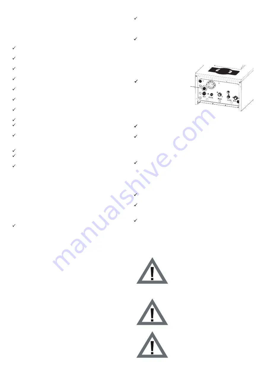
Connecting the drain 

pipework for the expansion 

relief val

ve

1.5. Boiler Start Up 

 Boiler start up must be performed certainly by gas safe 

engineer.

 Gas Type (Natural Gas / LPG), gas supply pressure 

(mbar), maximum DHW operating water pressure (bar) and 

electricity supply voltage on the information plate must be 

suitable with mains supply conditions. This is checked by 

gas safe engineer.

 After boiler start up, you should request information about 

operating the boiler and safety precautions from gas safe 

engineer.

1.6. Usage and Maintenance 

 Read carefully instructions and precautions in this manual 

against wrong usage which causes unsafe conditions.

 The boiler should be checked and serviced for general 

maintenance once a year. Maintenance and service 

operations must be carried out only gas safe engineer.

 Only a damp cloth should be used for cleaning the outer 

surface of the boiler and then the surfaces should be dried 

completely. Do not use chemical substances or solutions 

which cause rust and scratches in your boiler.

4

Summary of Contents for PROTEUS PREMIX 14 HM NG ERP UK

Page 1: ...INSTALLATION AND MAINTENANCE INSTRUCTIONS PROTEUS PREMIX CONDENSING BOILER PROTEUS PREMIX PPR 14 20 24 28 30 35 HM HCH HST...

Page 2: ......

Page 3: ...ULES AND WARNINGS 2 TECHNICAL DATA 3 NOTES ON THE DOCUMENTATION 4 SETUP 5 CONNECTIONS 6 INSTALLATION 7 OPERATION 8 INSPECTION AND MAINTENANCE 9 PART DEFINITIONS MAINTENANCE INSTRUCTIONS 10 INSPECTION...

Page 4: ...stalled in accordance with national and local requirements gas safety regulations relevant standarts and this manual by gas safe engineer 9 The boiler must be mounted against a closed wall 9 The boile...

Page 5: ...5 Seasonal Space Heating Energy Efficiency 91 11 91 4 92 2 92 4 92 92 9 Water Heating Energy Efficiency 83 6 83 6 83 6 83 9 82 8 82 8 Sound Power Level db A 49 49 49 49 49 49 Efficiency at Rated Heat...

Page 6: ...pansion Vessel lt 8 Weight Net kg 28 5 28 5 28 5 30 30 32 Weight Net only for HCH model kg 22 5 22 5 22 5 24 24 26 Dimesions HxWxD mm 678 410 288 Flue Lenghts C13 60 100 Max m 10 10 10 10 10 10 C13 80...

Page 7: ...centralheating co uk or installersfirst co uk for more information Table 2 Product Definition and Codes PRODUCT NAME PRODUCT CODE GC NUMBER PROTEUS PREMIX 14 HM NG ERP UK 8116941010 47 814 30 PROTEUS...

Page 8: ...the installation and initial start up of the boiler Instructions are given below Check Operating Instructions Installation and Maintenance Instructions and follow instructions before installation Carr...

Page 9: ...ervoir 19 Ignition Electrode 20 CH Return Temperature Sensor 21 CH Supply Temperature Sensor 22 Turbine 23 Flue Gas Sensor 3 3 2 HST Model System Boiler Figure 2 HST Boiler 11 12 16 1 15 10 9 8 2 4 3...

Page 10: ...CH HST Model Automatic Air Vent Expansion Vessel 8 liters Water ingress protection from flue Annual Maintanence Reminder 4 SETUP 4 1 Minimum Clearances 4 2 Dimensions Figure 4 Combi Mounting Clearance...

Page 11: ...tions 5 1 1 Flue Sizes Flue gas connections between the boiler and the flue terminal must be made using original components specially designed for the condensing boiler to ensure that the boiler opera...

Page 12: ...minimum distances required from the top and sides of the boiler Dimensions given in mm The installation must comply with the following minimum distances so that servicing and maintenance of the boiler...

Page 13: ...to the boiler The flue ducts are always wet Under cold or excessive humid weather conditions the water vapor inside the waste gas may condensate while leaving the flue 6 3 Mounting The Boiler Having d...

Page 14: ...ler CAUTION Disconnect power supply to prevent electrical shock before connecting the electrical supply CAUTION If the supply cord is damaged it must be replaced by the gas safe engineer in order to a...

Page 15: ...6 8 Installation for HCH Boiler External WRAS appoved filling loop must be added during installation Figure 15 Installation for HCH Boiler Heat Only Type Installation Expansion Vessel 15...

Page 16: ...rmostat outdoor sensor and timer must be performed certainly by gas safe engineer Room thermostat connection is installed by after removing bridge circuit Outdoor sensor is installed by connecting its...

Page 17: ...ton When your boiler fails the error code will start flashing on the display There are 2 types of errors lockout EXX and blocking FXX error When a lockout error condition occurs EXX the error must fir...

Page 18: ...e can be adjusted between 30 65 C 7 3 5 Comfort Mode The standard operating mode of the boiler is Comfort mode By pressing the Reset button Eco Comfort modes can be switched When Comfort mode is activ...

Page 19: ...on starts to light on the LCD at the first Access the menu When tS is selected by pressing on B RESET button 000 is seen on the screen When B RESET button is pressed again and password entry is displa...

Page 20: ...P33 OTC curve selection Num 0 0 0 0 0 0 System 1 Emas Hydroblok CCB Pakkens Configuration DHW P37 Water 2 Fugas Hydroblock Num 1 1 1 1 1 1 pressure circuit flow sensor circuit 3 Bitron Hydroblock Heat...

Page 21: ...is sufficient to press the Reset button once to exit the ASE mode AP Mode During this mode AP and water pressure values will appear on the screen Accessing to Inquiry Mode In Inquriy Menu gives detai...

Page 22: ...tively When Hi is selected by pressing on B button in the menu H01 is displayed on screen It is possible to select any parameter wished by pressing DHW E and DHW C buttons It is possibble to select an...

Page 23: ...9 Outdoor temperaure sensor error E15 Drift sensors check failed F40 The water pressure in the CH installation is too high E16 Supply sensor stuck_at test failed F47 Water pressure sensor is not conne...

Page 24: ...rect YES YES whether e ate trap and check conde a connected at YES NO NO are proper NO YES YES YES e ate trap if it electrode electrode NO float If electrode contact with water replace electrode conne...

Page 25: ...Replace the gas valve Dismount the gas valve connector Connect the power to the boiler Check whether the resistance at the connector ends coming from the circuit board is in the range of 23 25 V when...

Page 26: ...ter and return water Check whether resistance values are correct Internal bypass may be not functional Replace the 3 Way Valve Shaft Group Check whether error is gone after Reset YES Pump connection c...

Page 27: ...board side is latched or look for any loose contact Check whether cable connections are proper and without damage NO Remove igniton electrode and check is there any oxidation present YES Replace the...

Page 28: ...he gas valve connector Connect the power to the boiler Check whether the resistance at the connector ends coming from the circuit board is in the range of 23 25 V when the boiler is trying to ignite N...

Page 29: ...oard may be broken Replace main board Replace temperature sensors for CH supply and CH return waters YES NO E16 SUPPLY WATER TEMPERATURE SENSOR FAULT Check whether supply water temperature sensor is m...

Page 30: ...Main board may be broken Replace main board YES NO E18 TEMPERATURE SENSORS FAULT Temperature change on temperature sensor is too much 30 C Check whether the temperature sensor cables are working prop...

Page 31: ...nd without damage Replace CH return water temperature cables in case of any problem Check whether there is not any rusting corrosion or deformation inside where it touches to copper pipe or checking w...

Page 32: ...t doesn t disappear after reset replace the CH supply sensor Replace the main board NO YES E80 FAULT OF TEMPERATURE DIFFERENCE BETWEEN CH TEMPERATURE SENSORS CH return water temperature is higher than...

Page 33: ...pressure at gas valve inlet must be over 12 mbar Fix installation Press the Reset button Check whether ignition electrode cable electrode and electronic board side is latched or any loose contact YES...

Page 34: ...ads pressure Fill water into boiler up to 1 5 2 bars NO Access to i 05 parameter in the Inquiry parameter mode determine which temperature the sensor detects and compare it using another measuring dev...

Page 35: ...e the main board Pertinent intervention is applied according to the last fault in Fault history NO YES F25 Electronic Card Fault Check the error history and turn the boiler off and on again Relevant a...

Page 36: ...onnector on water pressure sensor when the power of the device is still on and measure the DC voltage Check whether the voltage is in the range of 4 9 5 1 V DC NO YES Replace the main board Replace th...

Page 37: ...loose contact Check the cables Replace them in case of any problem Replace the outdoor sensor Check whether fault is gone The problem is outdoor sensor Replace the main board YES YES NO NO Check wheth...

Page 38: ...d measure the DC voltage Check whether the voltage is in the range of 4 9 5 1 V DC YES Replace the main board NO YES Replace the pressure sensor Check whether fault is gone Check whether the pressure...

Page 39: ...oard F50 STORAGE TANK SENSOR FAULT Ensure that P00 1 for HM model P00 3 4 is used for HST model NO Boiler sensor cables may be not mounted or there may be a loose contact Check the cables YES Fix them...

Page 40: ...her any problem on PT1000 sensor Resistance Check YES Replace sensor in case of any problem Replace main board NO YES F52 DHW TEMPERATURE SENSOR FAULT NO DHW temperature sensor cables may be not mount...

Page 41: ...em if there is any damage Check whether any problem on flue gas temperature sensor Resistance Check Replace sensor in case of any problem Replace main board NO YES YES F58 Flue Gas Lock Up at High Tem...

Page 42: ...isappeared If not Supply return or dhw temperature sensor cables may be not mounted or there may be a loose contact Check the cable Fix them if not mounted replace them if there is any damage Check wh...

Page 43: ...0 2 24 kW G25 7 75 0 05 6250 1850 2750 3250 9 3 0 2 8 7 0 2 9 5 0 2 8 9 0 2 28 kW G25 8 8 0 05 6500 1900 2750 3300 9 3 0 2 8 7 0 2 9 5 0 2 8 9 0 2 30 kW G25 8 8 0 05 6900 2100 2750 3500 9 3 0 2 8 7 0...

Page 44: ...ounting Side Panel Unscrew 2 screws affixing the control panel to the side panels NOTE All part changes may be performed without removing the side panels Disassembly of side panels is give for informa...

Page 45: ...ECTOR NAME FUNCTION X1 Condensate Trap X2 Earth Outdoor Temperature Sensor X3 OpenTherm 3 0 Room Thermostat Program Timer DC Gas valve X4 Fan Driver Interface Flue Sensor Input DHW Instantaneous Senso...

Page 46: ...ctrode Mount the electrode and grounding cable as shown in the photo NOTE When mounting the electrode you must hear the locking sound as click Dismounting mounting fan cables Mount the cables of fan m...

Page 47: ...cable Flow sensor Hall Effect sensor in the tap water line shown in the photo Dismounting Mounting gas valve cable Dismounting Mounting surface type NTC and cable There are 2 surface type NTC on CH Su...

Page 48: ...nting motorized valve Remove the motorized valve by unlatching the clip holding the manifold and the motorized valve Unscrew the screw on the valve motor in order to replace the cable of the motorized...

Page 49: ...ve Remove firstly the hose at the end of safety valve Remove the connecting screw of lower chassis to the side panel Afterwards unscrew the nut on the manifold using an Allen screwdriver In order to r...

Page 50: ...as valve and gas pipe using a wrench Placing gas throttle washer Place the orifice washer between 2 seals into the gas valve Mounting dismounting Venturi Remove the clip fastening the gas pipe and ven...

Page 51: ...pump using a hand tool Unscrew the nut affixing the expansion tank and the flexible hose using a wrench Remove the gripper brackets of expansion tank Mounting dismounting the Main Exchanger group Und...

Page 52: ...Remove 4 screws of the burner door Follow the order of operations shown as wrench symbol inscribed on the burner door when dismounting and remounting Remove the Duroboard as shown in the photo Remove...

Page 53: ...terminal block as shown in the photo Mounting dismounting the main board Remove the main board by flexing the notches holding the main board on the control panel Mounting dismounting the mounting par...

Page 54: ...fold Remove the screws fastening the pump and to bottom consol Mounting dismounting of flow sensor Remove it using a wrench Dismounting of tap water filter Remove the filter on tap DHW inlet pipe usin...

Page 55: ...arge of exhaust gas from condensate trap s drain to outdoor Primary Relevant Error Codes Troubleshooting and Testing Method Visual inspection and cleaning of any dirt burrs etc inside condensate trap...

Page 56: ...amage and checking any abnormality of components circuits on the circuit board tarnishing solder cracks splits etc Maintenance Period No special maintenance requirement GAS VALVE Subject Description P...

Page 57: ...EXCHANGER Subject Description Part Function It is the main component in the central heating circuit enabling heat transfer to water Impact in Case of Faulty Operation 1 Failure to fully meet heating d...

Page 58: ...meeting tap water demand 2 When all radiator valves are closed it continues its function on water circulation itself internal by pass Impact in Case of Faulty Operation 1 In case of partial of full c...

Page 59: ...no heat is detected by temperature sensor error 2 No water is heated on tap water demand 3 Freeze protection function fails to work properly 4 Water instead of air comes out of pump air relief cock an...

Page 60: ...nterclockwise by pressing on the point shown with A using a No 2 screwdriver VENTURI Subject Description Part Function It is the component where gas coming from gas valve and air sucked in from silenc...

Page 61: ...age 2 Checking whether there is any rusting corrosion or deformation on the immersion probe 2 Resistance check Maintenance Requirement No special maintenance requirement Maintenance Period Testing Def...

Page 62: ...roper and without damage 2 Checking whether there is any rusting corrosion or deformation on the immersion probe 3 Resistance check Maintenance Requirement No special maintenance requirement Maintenan...

Page 63: ...ror Codes F37 F40 F47 Troubleshooting and Testing Method Visual Inspection and Testing 1 Checking whether cable connections are proper and without damage 2 Checking whether water inlet of water pressu...

Page 64: ...ing Method Visual Inspection 1 Checking whether cable connections are proper and without damage 2 Checking whether connectors on the 3 way motor are installed properly 3 Voltage Testing for central he...

Page 65: ...r discharge of water 2 High pressure error due to no discharge of water 3 Risk of leakage occurrence in plumbing where user continues to fill water after high pressure error Primary Relevant Error Cod...

Page 66: ...ectrode dimensional measurement controls 3 Ionization flow control 4 Replace electrode and electrode gasket together Maintenance Period Once a year or in any erros due to electrode according to instru...

Page 67: ...sting Method Measuring the expansion tank gas pressure Maintenance Period Once a year according to instructions below Maintenance Definition Maintenance Method Measuring Expansion Tank Gas Pressure Dr...

Page 68: ...age 2 Checking whether there is any oxidation etc around the flow sensor cable inlet 3 Voltage Testing 4 Filter cleaning and flow turbine group inspection Note If P00 parameter is 5 the boiler does no...

Page 69: ...getting its motion from 3 way motorized valve in order to ensure that boiler goes in the summer mode and the winter mode 2 It ensures the internal by pass function when the central heating valves are...

Page 70: ...o mixing of tap water with the water in the central heating system 4 Where the pressure of main tap water system is very low it may cause low pressure error by emptying water in the central heating sy...

Page 71: ...e any faults that are found Annually 12 Carry out the combustion analysis Measure the CO content CO content and the CO CO ratio For products with a rear air flue connection The combustion analysis can...

Page 72: ...After each time maintenance work is carried out 29 Open the service valves carry out the required leak tightness test Annually 30 Fill the product heating installation to the filling pressure specifi...

Page 73: ......

Page 74: ......

Page 75: ......

Page 76: ...RODUCTION EMAS MAK NA SANAY A Organize Sanayi B lgesi 3 K s m Mustafa Kemal Bulvar No 13 45030 MAN SA T RK YE Phone 90 236 213 00 21 Fax 90 236 213 08 59 E mail emas emas com tr www emas com tr SALES...

Reviews: