background image


5

Product Notation 


Table 1


Notation Description 

22 HS - 11 

Room sealed fan assisted gas water heater (11 lt/min.)


Technical Data 


Room sealed gas water heater is a C type appliance. C type appliances have a sealed combustion 
chamber. Required fresh air for combustion is provided independently from the installation room by 
concentric air/flue ducts and products of combustion can be also discharged by the same air/flue 
ducts.  
 

Table 2 

22 HS -11 

Unit 


Gas Category  
Type of gas 
 
Type 


Performances 

  P

min

Min. Heat Output 

  P

max

Max. Heat Output 

  Q

min

Min. Thermal Load


  Q

max

Max. Thermal Load 


Gas Consumption* 

 Natural Gas  (Max.) 
 Natural Gas  (Min.) 
 LPG  (Max.) 
 LPG  (Min.) 


Gas Supply Pressure 


Natural Gas  

  LPG 


Hot Water 


Min. Flow Rate For Activating 

 Max. Flow Rate  
 Min. Operating Pressure 
 Max. Operating Pressure 
 Set Temperature Range 


General 

 Electrical Supply 
 Electrical Power Consum. 
 Dimensions (HxWxL) 
 Weight (Net) 


II 

2H 3B/P


Natural gas -  LPG 


12


19,7 

9,2 

22 


2,29 
0,96 
1,72 
0,72 


20 

30 


2,5 

11 (

Δ

t=25) 

0,2 

10 

35 – 60 


230V – 50Hz 

65 

640x360x240 

18 


kW 
kW 
kW 
kW 


m

3

/h 

m

3

/h 

kg/h 
kg/h 


mbar 
mbar 


lt/min 
lt/min 

bar 
bar 

o


V AC / Hz 

watt 

mm 

Kg 

*

for gas consumption calculation; Natural gas: Hu=9,59 kWh/m3 

LPG: Hu=12,793 kWh/kg 


Summary of Contents for 22 HS -11

Page 1: ...22 HS 11 Room Sealed Electronic Gas Water Heater INSTALLATION AND USER S OPERATING INSTRUCTIONS ...

Page 2: ...TION Selection Of The Location Mounting Heater CONNECTIONS Flue Connection Gas Supply Water Systems Electricity Supply START UP Final Checks And Operations Before Start up Control Panel Operating The water Heater GAS TYPE CONVERSION Gas Pressure Adjustments Replacement Of The Burner Injectors Parameter Adjustment FAULT ERROR FINDING MAINTENANCE STANDARDS AND REGULATIONS ...

Page 3: ...terial in condition that the instructions and precautions in this manual must be obeyed The service operations and general maintenance must be carried out only by qualified person The warranty certificate must be registered by Service in the installation day Your appliance need not any repairs if operated according to this manual For assistance or additional information consult qualified person in...

Page 4: ... completed in accordance with the relevant regulations and standarts by user Gas Type Conversion The appliance should be purchased depending on operating gas type In case of a demanding gas type conversion this is made with charge Gas type conversion from LPG to natural gas or from natural gas to LPG must be carry out only by qualified person After gas type conversion gas leak test must be perform...

Page 5: ...for use with either Natural Gas or LPG The water heater has space saving design which provides easy servicing and maintenance It has also a elegant appearance with compact dimensions 640x360x240 mm Microcontroller board provides all the functionality and safety of the water heater Burner is made of stainless steel withstands thermal stress Burner performs silently and provides efficient and clean ...

Page 6: ...ces Pmin Min Heat Output Pmax Max Heat Output Qmin Min Thermal Load Qmax Max Thermal Load Gas Consumption Natural Gas Max Natural Gas Min LPG Max LPG Min Gas Supply Pressure Natural Gas LPG Hot Water Min Flow Rate For Activating Max Flow Rate Min Operating Pressure Max Operating Pressure Set Temperature Range General Electrical Supply Electrical Power Consum Dimensions HxWxL Weight Net II 2H 3B P ...

Page 7: ...he instructions on the water heater package should be considered during transportation and storage The product is covered with a cardboard box of which dimensions are 640x360x240 mm HxWxL and supported by upper and lower styrofoams fig 2 Fig 2 ...

Page 8: ...mostat 85 0 C 11 Flow Switch 12 Control Panel 13 On Off Knob 14 Temperature Control Knob 15 Water Inlet Cold 16 Gas Inlet 17 Water Outlet Warm INSTALLATION Selection Of The Location The appliance must be installed in accordance with gas safety regulations and relevant standards Additionally the clearances around the boiler should be as shown in fig 4 in order to make service maintenance and usage ...

Page 9: ...NG Do not block the air vents which provide fresh air to the installation room WARNING The water heater location and air flue terminal position must obey national and local requirements gas safety regulations and relevant standarts The water heater is not suitable for external installation It should be within in the building In case of gas leakage it is necessary to vent the installation room acco...

Page 10: ...nd local requirements The air flue ducts should be fitted at a slight 10 or 20 downwards incline to prevent any water or condensation from entering the combustion chamber Mounting Heater Having determined the heater location Use the paper template to mark out the positions of the fixing holes of wall and mounting brackets Drill the wall and fix the wall bracket to the wall with the 3 screws Hang u...

Page 11: ...should be fitted at a slight 10 or 20 downwards incline to prevent any water or condensation from entering the heater The air flue kit given with your room sealed fan assisted appliance is only suitable for horizontal air flue design If the air flue kit length is insufficient additional flue accessories should be ordered through qualified service Do not use any other type brand name of flue parts ...

Page 12: ...ber of 900 elbow to be used is 3 a b c fig 8 Mounting the restrictor The restrictor should be mounted on the fan outlet according to the length of the air flue connection to provide efficient combustion and suitable combustion products Table 3 Table 3 Product Elbow L m Lmax m restrictor mm 1x900 1 43 1x900 1 2 45 1x900 2 3 47 1x900 3 4 4 2x900 1 45 2x900 1 2 47 2x900 2 3 3 3x900 1 47 22 HS 11 3x90...

Page 13: ...e pipes connections are shown in fig 10 fig 10 A suitable valve should be mounted on the gas inlet and the water circuits In addition a water filter should be mounted on cold water 1 2 inlet The connection between the appliance and gas supply must be made with a flexible pipe ...

Page 14: ... is not intented for use by person including children with reduced physical sensory or mental capabilities or lack of experience and knowledge unless they have been given supervision or instruction concerning use of appliance by a person responsible for their safety Children should be supervised to ensure that they do not play with the appliance Open hot water tap to check the water circuit Check ...

Page 15: ...ock out condition LCD Display Water heater functions water temperature set and actual values fault error conditions can be seen on LCD Fig12 fig 12 A Temperature value B Water demand is ON When the hot water tap is turn on the tap symbol appers on the LCD C Fault Error condition or Service mode In case of error error code appers automatically on the LCD display and the spanner symbol appears on th...

Page 16: ...n 35 0 C and 60 0 C fig 14 Setting value appears on the LCD blinks after four seconds actual water temperature will appear instead of the set value The heater will modulate to the desired temperature fig 14 The reset procedure to reset the system from lockout fig 15 Turn the temperature control knob to the outside of the reset zone in the adjustment zone Turn the temperature control knob into the ...

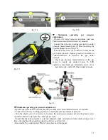
Page 17: ...ing gas pressure must be set by means of the adjusment screws that are on top of the gas valve The heat output directly depends on the operating pressure When the operating gas pressure range is adjusted minimum and maximum heat output is also adjusted mechanically First operate the water heater at maximum load while adjusting maximum operating pressure and operate the appliance at minimum load wh...

Page 18: ...d value In LPG operation maximum gas adjusment screw 4 is tigtened to the end for 28 mbar supply pressure Fig 17c fig 18 Minimum operating gas pressure adjustment Operate the water heater at minimum load use Parameter menu detailed in service manual Connect the tube of a clocking gas meter to outlet pressure measurement point 2 Turn the plastic srew 3 clocwise to increase the outlet gas pressure a...

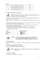
Page 19: ...front panel and push the panel up and remove Pull the control panel outwards fig 17b Undo the 4 screws which fasten the manifold to the burner to remove the burner Fix the suitable burner injectors according to type of gas 11 pieces of injectors used Reassemble in the reverse order Table 5 Injectors Diameter Natural Gas 1 25 mm LPG 0 75 mm WARNING In case of gas leak fire or explosion hazard prope...

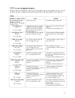
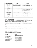
Page 20: ...voltage is not correct after 5 ignition trial Reset procedure is necessary Anomaly disappears if mains voltage is correct overtemperature Ht ON key icon blink If the water temperature exceeds 70 o C over temperature occurs Water heater will remain in this error mode till water temperature drops into the operating range If repeated consult qualified services Failure water temperature sensor Pb ON k...

Page 21: ...ecked and serviced for general maintenance once a year Maintenance and service operations must be carried out only by qualified person Only a damp cloth should be used for cleaning the outer space of the heater and then the surfaces should be dried completely Do not use chemical subtances or solutions which cause rust in your appliance STANDARDS AND REGULATIONS During the installation and operatio...

Reviews: