Rev. 01/11
-1.12-
TFXL-X
or disconnected, connect the positive supply wire and ground to the
appropriate field wiring terminals in the flow meter. See
Figure 1.5
.
A wiring diagram decal is located on the inner cover of the flow
meter enclosure.
If the flow meter is only to be utilized as a flow rate indicator or
totalizer, no further wiring will be required. Skip to Page 1.17.
PART 1 - TRANSMITTER INSTALLATION
Figure 1.5
DC Power Connection
11-30 VDC
DC Ground
11 to 30 Vdc
IMPORTANT NOTE:
Not following instructions properly may impair
safety of equipment and/or personnel.
IMPORTANT NOTE:
Must be operated by a power supply suitable
for the location.
IMPORTANT NOTE:
Do not connect or disconnect either power or
outputs unless the area is known to be non-
hazardous.
IMPORTANT NOTE:
Do not connect the interface cable between a
TFXL and a personal computer unless the
area is known to be non-hazardous.
!
!
!
!
Summary of Contents for TFXL series
Page 2: ......
Page 10: ...Rev 01 11 1 8 TFXL X PART 1 TERMINOLOGY PC INTERFACE CABLE ...
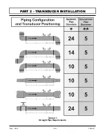
Page 23: ...Rev 01 11 2 3 TFXL X PART 2 TRANSDUCER INSTALLATION Table 2 1 Straight Pipe Requirements ...
Page 52: ......
Page 53: ...APPENDIX ...
Page 54: ......
Page 55: ......
Page 69: ......


