Application Assistance 1.800.234.8731 (847.662.6633)
Page 7
LED OUTPUT OPTION
Dynapar Exclusive:
The LED Output Indicator Option makes Dynapar
brand the only encoders that show they are installed and operating
correctly.
Green light emitting diodes (LEDs) are connected to the signal outputs
of the encoder. Set to turn on when the output voltage falls below 2
volts, the LEDs will alternate as the encoder shaft is rotated. For
models with differential, or complimentary outputs, a green LED is
connected to the non-inverting output and a red LED is connected to
the inverting output. In this case, the LED will alternate green-red as
the non-inverting output, then the inverting output alternately pulse.
A visual indication of the status of the Index output - also called the
Reference, Zero or Marker pulse - makes alignment of the electrical
output to a physical point on the machine or process much easier. The
encoder shaft is simply rotated until the Index LED turns on, then the
shaft coupling is tightened to keep the encoder aligned with the
mechanics.
Constant green or red LEDs indicate the corresponding output is
permanently grounded, whereas no (green or red) indicating shows
that an output is tied to the power supply. Yellow indications occur
when both the green and red LEDs turn on at the same time, pointing
to a grounded signal at the output that fails to turn off.
The LED Output Indicator Option is packaged in a sealed extruded
aluminum housing, providing a rugged, washdown rated and high
noise immunity feature that does not derate the encoder performance.
Current draw is only 0.5 mA per channel, and the circuitry works with
all electrical output configurations.
SPECIFICATIONS
Note: The following LED option specifications may supercede
standard encoder specifications
LED Characteristics:
On when output signal is < 2 VDC Input
Power:
5 to 26 VDC at 0.5mA per channel; 0.5mA max for unidirec-
tional, 1.0mA max for bidirectional, 1.5mA max for bidirectional with
Index
Electrical Protection:
Over-voltage, reverse voltage and short-circuit
protected
Noise Immunity:
Tested to IEC801 level 3 for Electro Static Discharge,
Radio Frequency Interference and Electrical Fast Transients
Standard Operating Temperature:
-40 to +85
°
C (0 to +70
°
C with
4469 line driver, see
“
Ordering Information
”
). At shaft speed above
3000 RPM, derate 10
°
C per 1000 RPM
Extended Temperature Range:
-40 to +100
°
C (See ordering
information)
Storage temperature:
-40 to +100
°
C
Shock:
50 G
’
s for 11 milliseconds duration
Vibration:
5 to 2000 Hz @ 20 G
’
s
Humidity:
to 98% without condensation
Enclosure Rating:
NEMA12 / IP54 standard; NEMA4 / IP66 when
ordered with shaft seal
A
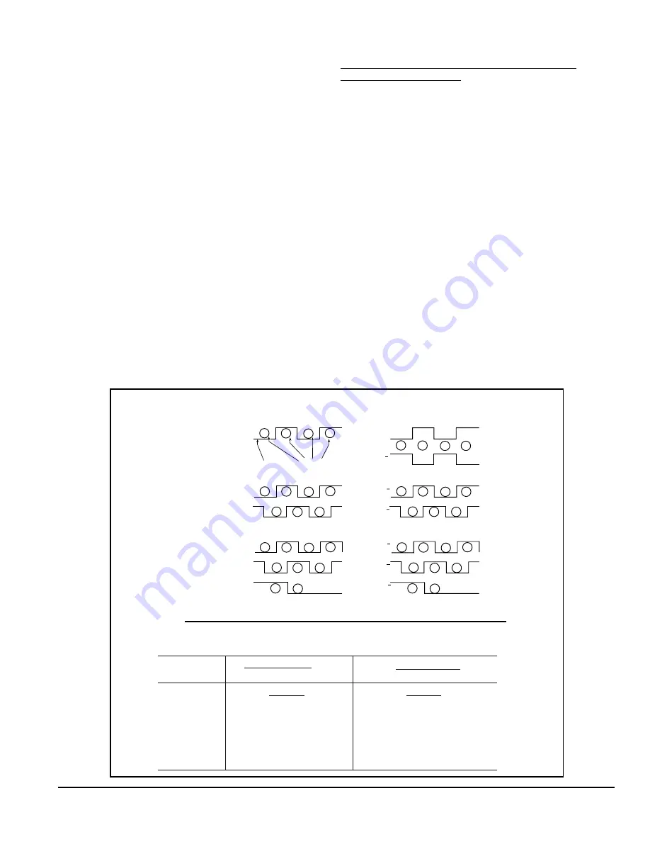
TYPICAL OUTPUT WAVEFORMS AND LED INDICATIONS
Single-Ended
Bidirectional
A
B
Bidirectional
With Index
A
B
Z
Unidirectional
Differential
A/A
B/B
A
A
A/A
B/B
Z/Z
Output Voltage
Output Indicator
G
G
o
o
G
G
G
G
o
o
o
G
G
G
G
G
o
o
o
o
G
G
G
G
G
R
R
R
R
G
G
G
G
R
R
R
R
R
G
G
Note:
G
= Green;
R
= Red;
O
= Off
SINGLE-ENDED
Alternate Green/Off
HOW TO USE THE LED OUTPUT INDICATIONS
TO TROUBLESHOOT WIRING PROBLEMS
ABNORMAL
NORMAL
1. No LEDs come on
2. LED stays Green
3. LED stays Red
4. Green LED stays Off
5. Red LED stays Off
6. LED alternates Green/Yellow
7. LED alternates Red/Yellow
1. No power, or reversed power
2. Signal tied to Common
3. Compliment tied to Common
4. Signal tied to Power
5. Compliment tied to Power
6. Signal tied to Common, Compliment OK
7. Compliment tied to Common, Signal OK
PROBLEM
SYMPTOM
DIFFERENTIAL
Alternate Green/Red


