


6
2
INSTALLATION
This chapter describes the installation procedure for your switch.
Packing List
Your package should come with the equipment listed below. If any item is missed or damaged, notify your dealer
immediately.
♦
One HomePNA Switch DYNAMIX DH - 114 (or DYNAMIX DH - 114 M).
♦
One External AC Power Cord.
♦
One RS-232 Console Cable (DB9-MiniDin8).
♦
One Cascaded Console Cable (MiniDin8-MiniDin8).
♦
One User’s Guide.
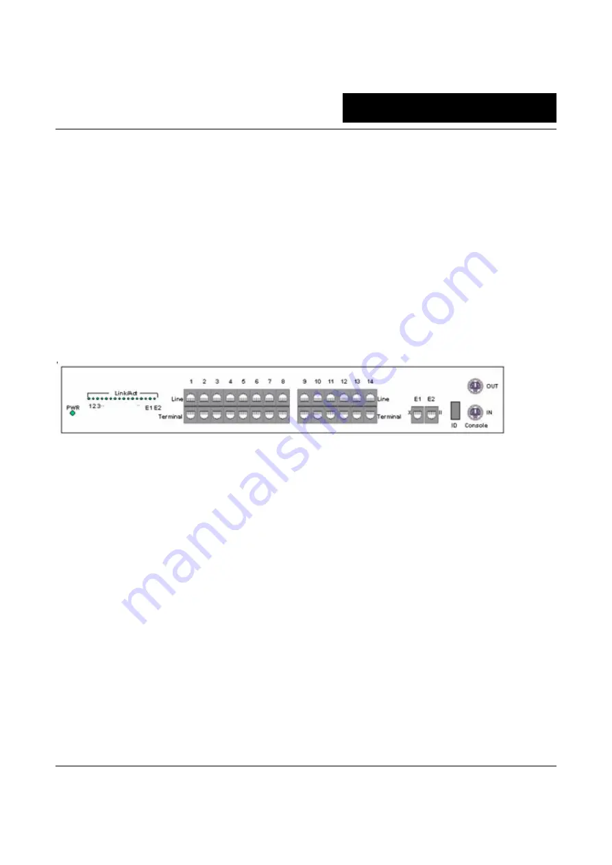
Front Panel
See the following Figure 1.
Figure 1 Front panel of DYNAMIX DH - 114/DYNAMIX DH - 114 M
Connectors
1.
1 to 14: Fourteen HomePNA ports with dual-row RJ-45 connector labeled ‘1’ to ‘14’. Each HomePNA port has
one ‘Line’ connector (upper row) and one ‘Terminal’ connector (bottom row).
2.
E1, E2: These two Ethernet ports are used to cascade with other DYNAMIX DH - 114 (DYNAMIX DH - 114 M)
or standard Ethernet Switch/Hub. See the following section “Connecting the Cables” in this Chapter.
3.
Console IN/OUT: The console IN port may connect to the serial COM port of PC for local configuration. You
can cascade the console IN/OUT port through a lot of switches for configuration. See “Connecting the
Cables”.
LED Indicators
1. PWR: Lighting up when power on.
2. Link/Act (1 to 14): Each led represents the responding HomePNA port. Flashing when there is any data traffic.
3. Link/Act (E1, E2): Lighting up when the Ethernet link is active, and flashing when there is any data traffic.
4. ID: 7-segment led shows the switch ID.
Connecting the Cables
The HomePNA ‘Terminal’ port (1 to 14) requires standard twisted phone wiring for user attached to the same
phone line via the PNA adapter. And the HomePNA ‘Line’ port (1 to 14) connects to the PSTN/PABX for your
original phones. The Ethernet port (E1 and E2) is unshielded twisted pair (UTP) 100Base-T cabling. All 16 ports
work as a standard 16 ports Ethernet switch in the LAN (Local Area Network) environment. See Figure 2 for the
cabling of single HomePNA switch DYNAMIX DH - 114 or DYNAMIX DH - 114 M.
You can stack more DYNAMIX DH - 114s to accommodate more HomePNA users by cascading DYNAMIX DH -
114's Ethernet port and Console port together. For example, connect two or three DYNAMIX DH - 114 with
Ethernet cable from one switch's E1 port (MDI-X connector) to the next switch's E2 port (MDI-II connector). And


